Proximity sensors are indispensable components in modern industrial automation, offering non-contact detection of objects with high reliability and speed. Proper debugging and configuration are critical to ensure optimal performance, minimize false triggers, and extend sensor lifespan. This guide provides a systematic approach for engineers to debug, configure, and integrate proximity sensors effectively.
1. Pre-Installation Checks and Understanding Specifications
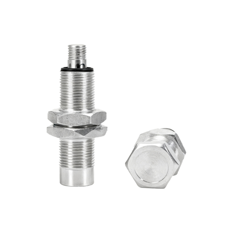
Before physical installation, thoroughly review the sensor datasheet. Key parameters include sensing distance (rated and effective), supply voltage (e.g., 10-30 VDC), output type (PNP/NPN, NO/NC), current rating, and housing material (e.g., brass, stainless steel). Ensure the selected sensor type—inductive (for metals), capacitive (for various materials including liquids), or ultrasonic—matches the application. Verify the environmental specifications for temperature, humidity, and ingress protection (IP rating) against the operating conditions.
2. Mechanical Installation and Alignment
Mount the sensor securely using appropriate brackets, ensuring no excessive vibration. The sensing face must be parallel to the target object. Maintain the recommended installation distance: typically, leave a clearance of at least 2-3 times the sensor's diameter from surrounding metal to avoid shielding effects. For cylindrical barrels, use non-ferromagnetic mounting nuts. Align the sensor axis perpendicular to the target's approach path for consistent detection. After mounting, perform a preliminary check by powering the unit and observing the indicator LED (if present) as a target passes.
3. Electrical Wiring and Power Supply
Disconnect all power before wiring. Follow the wiring diagram precisely. For 3-wire DC sensors:
- Brown wire: Connect to DC+ (e.g., +24V).
- Blue wire: Connect to DC- (0V or ground).
- Black wire (often): The output signal line. Connect to the PLC input or load.
Ensure correct polarity. Use shielded cables in electrically noisy environments, grounding the shield at the controller end only. Incorporate a surge suppressor for inductive loads like relays or solenoids. Use a stable, regulated power supply; voltage fluctuations can cause erratic behavior. Check for proper grounding of both the sensor and the metal chassis.
4. Configuration and Sensitivity Adjustment
Many modern sensors feature potentiometers or teach-in functions for fine-tuning.
- Inductive Sensors: Adjust the sensitivity potentiometer (if available) to set the exact switching point. Use a target made of the correct material (e.g., mild steel for reference). Gradually bring the target closer until the output switches, then back it off slightly to create a safety margin, accounting for mechanical tolerances and temperature drift.
- Capacitive Sensors: These often have two adjustments: sensitivity and response time. Sensitivity controls the detection threshold for different materials. To set it, place the target object at the desired operating distance and increase sensitivity until the output activates. Response time can be slowed to ignore fast-moving debris or sped up for high-speed counting.
- Ultrasonic Sensors: Configure parameters like measuring window, response time, and analog output scaling via pushbuttons or software. Ensure the object is within the sound cone and free from acoustic interference.
5. Debugging Common Issues
Methodical debugging resolves most field problems.
- No Output/Sensor Not Triggering:
1. Verify power supply voltage at the sensor terminals with a multimeter.
2. Check wiring connections and polarity.
3. Confirm the target is within the sensing range and made of a detectable material.
4. Test by using the factory-default sensing object (e.g., a steel plate for inductive).
5. Inspect for accumulated debris on the sensing face.
- Erratic/False Triggering:
1. Look for environmental interference: weld slag, metal dust, strong electromagnetic fields, or adjacent sensors interfering. Increase separation between sensors.
2. Check for unstable power supply or voltage spikes. Use an oscilloscope if necessary.
3. For capacitive sensors, reduce sensitivity if detecting background objects or moisture.
4. Ensure the target object is not vibrating or oscillating in the detection zone.
5. Verify the load current does not exceed the sensor's maximum rating.
- Short Sensing Range:
1. Check if the target material differs from the specification (e.g., aluminum vs. steel for inductive sensors requires a reduction factor).
2. Decrease the sensitivity setting if it's too low.
3. Clean the sensing face.
4. Ensure the operating voltage is at the nominal level.
6. Advanced Diagnostics and Integration
For networked or IO-Link sensors, use manufacturer software for advanced diagnostics. Monitor parameters like switching frequency, temperature, and operating hours. Set up hysteresis to prevent output chattering when a target is at the exact switching point. When integrating with