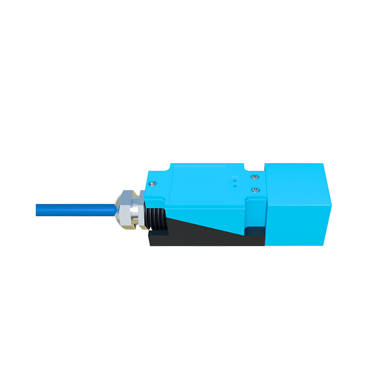
In industrial automation and control systems, proximity sensors are indispensable components for non-contact detection of metallic or, in some cases, non-metallic objects. While much attention is given to selecting the correct sensor type—inductive, capacitive, or photoelectric—the integrity and performance of the entire sensing loop are fundamentally dependent on the proper installation and handling of the signal wiring. Incorrect wiring practices are a leading cause of sensor malfunction, intermittent operation, and system downtime. This article outlines critical best practices for proximity sensor signal line installation, shielding, and routing to ensure reliable, long-term operation in harsh industrial environments.
The core function of the signal wire is to transmit the sensor's output state—typically a discrete ON/OFF signal—to the controller, such as a PLC. For DC sensors, this involves two or three wires: power supply positive (brown), power supply negative/ground (blue), and the signal output (black). For AC sensors, the wiring typically involves two wires that carry both power and the switched output. The first and most critical step is meticulous adherence to the manufacturer's wiring diagram. Connecting the supply voltage incorrectly can cause immediate and permanent damage to the sensor's internal electronics. Always verify the voltage rating (e.g., 10-30V DC, 90-250V AC) and the output type (NPN sinking or PNP sourcing for DC) before making any connections.
Once correctly connected, the physical routing of the signal cable becomes paramount. A fundamental rule is to separate sensor signal lines from power lines and high-energy cables, such as those feeding motors, drives, or welding equipment. These cables generate strong electromagnetic interference (EMI) and inductive noise. Running sensor wires in parallel and in close proximity to these noise sources can induce voltages in the signal line, leading to false triggering or signal loss. Maintain a minimum separation distance of 20-30 cm. If cables must cross, they should do so at a 90-degree angle to minimize the area of inductive coupling.
For environments with high levels of electrical noise, the use of shielded cables is non-negotiable. The shield, typically a braided copper mesh or foil layer surrounding the inner conductors, acts as a barrier to capacitive coupling and a path to ground for EMI. The correct termination of the shield is crucial; a poorly grounded shield can act as an antenna, worsening noise problems. The best practice is to ground the shield at one end only, typically at the control panel end, to the system's ground reference point. Avoid grounding both ends, as this can create ground loops—circulating currents between different ground potentials that introduce noise. The shield should be connected to a dedicated grounding terminal, not to a painted or anodized surface, ensuring a solid, low-impedance connection.
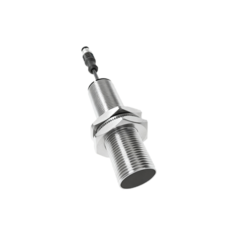
Cable protection is another vital consideration. In industrial settings, cables are exposed to mechanical stress, abrasion, oils, coolants, and extreme temperatures. Always use cables with appropriate insulation ratings (e.g., oil-resistant, PVC, or PUR jackets). Route cables within cable carriers, conduits, or along protected channels to prevent crushing, stretching, or cutting. Pay special attention to the cable entry point at the sensor itself. Use sensors with integrated, strain-relief cable glands or connectors. If a separate gland is used, ensure it is properly tightened to provide an IP-rated seal against dust and moisture, which can cause corrosion and short circuits over time.
Finally, consider the electrical characteristics of the entire circuit. Long cable runs introduce resistance and capacitance, which can attenuate the signal, especially for higher-speed switching applications. Adhere to the manufacturer's specified maximum cable length. For very long runs or high-noise environments, consider using signal conditioners, repeaters, or analog-to-digital converters located closer to the sensor. Always perform a comprehensive system check after installation. Use a multimeter or an oscilloscope to verify the signal integrity at the PLC input, ensuring a clean, sharp transition between the ON and OFF states without noise spikes or dropouts.
In summary, the reliability of a proximity sensor is only as good as its signal path. By rigorously applying these wiring principles—correct connection, physical separation from noise sources, proper use and grounding of shields, robust mechanical protection, and attention to circuit length—engineers and technicians can dramatically reduce failures, enhance system stability, and minimize costly unplanned downtime. Treat the signal wiring with the same level of importance as the sensor itself.