In the realm of industrial automation and machine control, proximity sensors are indispensable components. Their primary function is to detect the presence or absence of an object without physical contact. While specifications like sensing distance, material compatibility, and output type are often the initial focus, one critical parameter that fundamentally impacts system performance is response time. This article delves into the intricacies of proximity sensor response time, exploring its definition, influencing factors, and implications for application design.
What is Response Time?
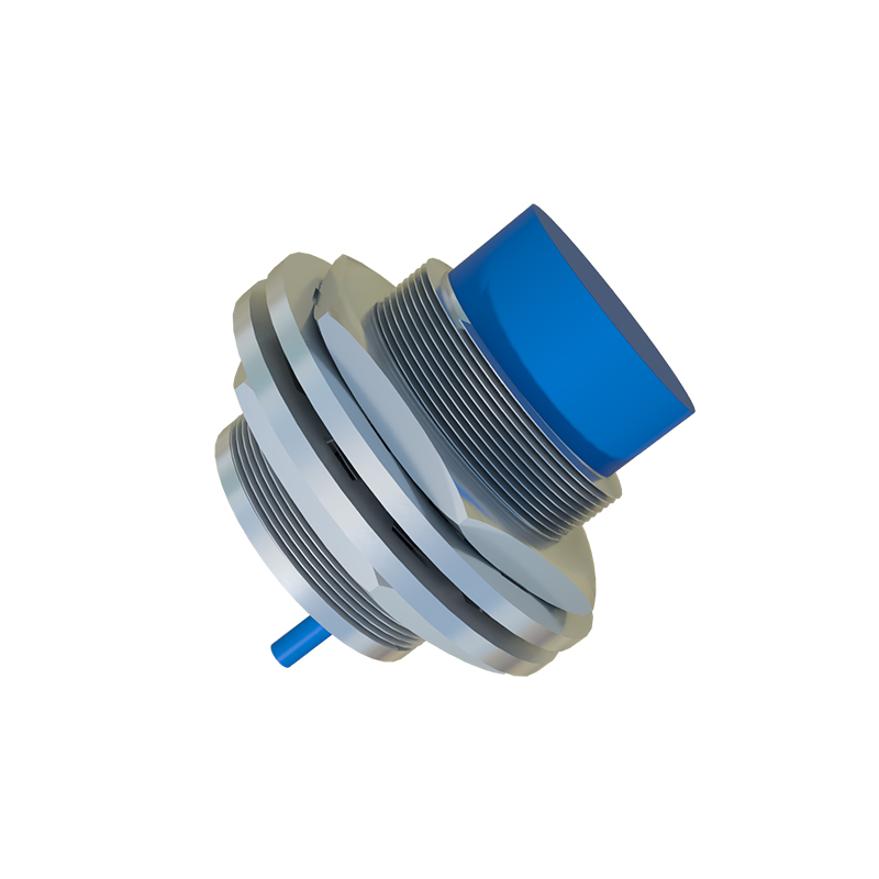
Response time, typically measured in milliseconds (ms) or microseconds (µs), is the total time delay between a change in the sensing condition (the target entering or leaving the sensing field) and the corresponding change in the sensor's output signal. It is often broken down into two components:
1. Approach Response Time: The delay from when a target enters the effective sensing range until the output switches state (e.g., from OFF to ON).
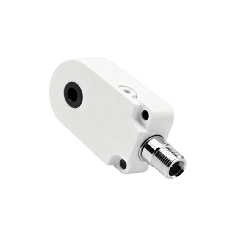
2. Release Response Time: The delay from when a target leaves the sensing range until the output returns to its original state (e.g., from ON to OFF).
These values are not always symmetrical and are specified in the sensor's datasheet under standard conditions.
Key Factors Influencing Response Time
Several intrinsic and extrinsic factors determine how quickly a proximity sensor can react:
Sensor Technology: The underlying technology is the primary determinant.
Inductive Sensors: Common for metal detection. Their response time is generally fast, often ranging from 0.1 ms to 2 ms, influenced by oscillation frequency and circuit design.
Capacitive Sensors: Used for detecting various materials. They can be slightly slower than inductive types due to the charging/discharging cycles involved, often in the range of 10-50 ms.
Photoelectric Sensors: Utilize light beams. Response times can be extremely fast (e.g., 50 µs for fiber-optic amplifiers) but depend on light source modulation and receiver circuit speed.
Ultrasonic Sensors: Measure time-of-flight. Their response is inherently slower due to the speed of sound and signal processing requirements, often from 10 ms to over 100 ms.
Output Circuit Type:
PNP/NPN Transistor Outputs: Solid-state outputs offer very fast switching, typically under 1 ms.
Analog Outputs (4-20mA, 0-10V): The response time here refers to how quickly the output current/voltage can track a change in distance. It is usually specified as a time constant (e.g., 5 ms).
Relay Outputs: Incorporate mechanical contacts, making them significantly slower (often 5-15 ms) and subject to wear.
Target Characteristics: For inductive sensors, the target material (steel, aluminum, copper), size, and approach speed affect the eddy current generation and thus the response. A smaller or slower-moving target may result in a marginally longer detection time.
Environmental Conditions: Extreme temperatures, strong electrical noise, or contamination on the sensor face can degrade performance and increase response time variability.
Sensor Configuration & Filtering: Many modern sensors feature built-in response delay adjustments or noise filters (e.g., leading-edge or trailing-edge delay functions). While these enhance stability in noisy environments, they intentionally add to the overall response time.
Why Response Time Matters in System Design
Ignoring response time can lead to system inefficiencies, errors, or even failures.
High-Speed Counting & Sorting: In packaging or assembly lines, sensors must detect rapidly passing items. A sensor with a 5 ms response time cannot accurately count objects spaced less than 5 ms apart.
Precision Positioning: In robotics or CNC machinery, the sensor signal triggers a critical action (e.g., stopping a spindle). A slow response introduces positional error proportional to the machine's speed.
Synchronization: In multi-sensor systems, mismatched response times can cause logic sequence errors in PLC programs.
Safety Applications: While not typically used as primary safety devices, sensors in monitoring roles must have a predictable and fast enough response to contribute to safe machine operation.
Calculating and Applying Response Time
A practical rule involves comparing the sensor's response time (t_sensor) with the required system reaction time. For a target moving at speedv, the allowable positional errord_error can be approximated as:d_error ≈ v t_sensor. Engineers must select a sensor wheret_sensor is significantly less than the process timing budget.
Testing and Specification Reliance
Always refer to the manufacturer's datasheet for guaranteed minimum/maximum response time values, noting the test conditions. In critical