Infrared proximity sensors are widely used in various applications, from robotics and automation to consumer electronics and security systems. These sensors operate by emitting infrared (IR) light and detecting its reflection from nearby objects, allowing for non-contact distance or presence detection. Understanding the circuit diagram of an infrared proximity sensor is crucial for engineers and hobbyists looking to design, troubleshoot, or integrate these devices effectively. This article delves into the key components and working principles of a typical IR proximity sensor circuit, providing a detailed explanation suitable for industry professionals.
A basic infrared proximity sensor circuit consists of three main sections: the IR transmitter, the IR receiver, and the signal processing unit. The transmitter section typically includes an infrared LED (Light Emitting Diode) that emits modulated IR light. Modulation is essential to distinguish the sensor's signal from ambient infrared radiation, such as sunlight or indoor lighting, which could cause false readings. A common modulation frequency ranges from 30 kHz to 40 kHz. The LED is driven by a simple oscillator circuit, often built using a 555 timer IC or a microcontroller, which generates a pulsed signal to power the LED efficiently. This pulsed operation not only reduces power consumption but also enhances the sensor's immunity to interference.
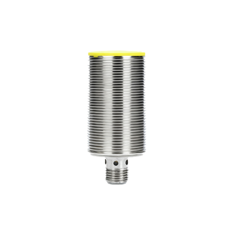
The receiver section features an IR photodiode or phototransistor tuned to detect the modulated IR light reflected from an object. These components are sensitive to the specific wavelength emitted by the IR LED, usually around 940 nm. When IR light hits the photodiode, it generates a small current proportional to the light intensity. In the circuit, this current is converted into a voltage signal through a transimpedance amplifier or a simple resistor network. To filter out unwanted signals, the receiver often incorporates a demodulator, such as a dedicated IR receiver module (e.g., TSOP series), which only responds to the predefined modulation frequency. This ensures that only the reflected IR pulses from the transmitter are processed, minimizing errors from external IR sources.
Signal processing is the final stage, where the received signal is conditioned to produce a usable output. The output from the IR receiver is typically a digital signal that goes high or low based on the presence of a reflected IR pulse. This signal can be fed directly into a microcontroller or logic circuit for further action. In analog designs, the signal might be amplified and compared with a threshold voltage using an operational amplifier (op-amp) comparator. The comparator's output switches when the reflected signal exceeds the threshold, indicating an object within a certain range. Adjusting the threshold or using variable resistors allows calibration of the sensor's sensitivity and detection distance.
Power supply considerations are vital for stable operation. Most IR proximity sensors operate at low voltages (e.g., 3.3V or 5V DC), making them compatible with common electronic systems. Decoupling capacitors should be placed near active components like ICs to suppress noise and voltage fluctuations. Additionally, proper PCB layout practices—such as separating analog and digital grounds and minimizing trace lengths—can enhance performance by reducing crosstalk and interference.
In practical applications, engineers might encounter challenges like ambient light interference, varying reflectivity of objects, or limited detection range. To address these, advanced circuits may include automatic gain control (AGC), temperature compensation, or multiple IR LEDs for broader coverage. For instance, in robotics, sensors with adjustable pulse widths can improve accuracy in dynamic environments. Testing with an oscilloscope can help visualize the transmitted and received signals, aiding in debugging and optimization.
Overall, mastering the infrared proximity sensor circuit diagram empowers professionals to customize sensors for specific needs, whether it's increasing range, enhancing precision, or integrating with IoT devices. By grasping each component's role—from the oscillating transmitter to the filtered receiver and processed output—engineers can innovate in fields like industrial automation, touchless interfaces, and smart home systems, driving efficiency and safety in modern technology.