Proximity sensors are integral components in modern smartphones, primarily responsible for detecting the presence of nearby objects without physical contact. Typically based on infrared (IR) technology, these sensors enhance user experience and device efficiency. This guide details the configuration and calibration processes from an engineering perspective.
The core of a smartphone proximity sensor is an IR LED paired with an IR photodetector. The LED emits an infrared light beam. When an object, like a user's ear during a call, comes close to the screen, the light reflects back to the photodetector. The sensor's controller IC measures the intensity of the reflected light to determine proximity. The primary function is to disable the touchscreen and turn off the display during calls to prevent accidental touch inputs and save power.
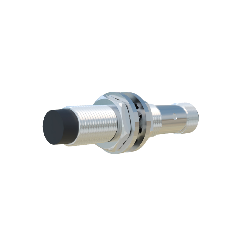
Initial Hardware Integration and Circuit Configuration
The first step involves correct hardware placement. The sensor assembly, often combined with the ambient light sensor in a single module, must be positioned behind a dedicated window on the front bezel. This window must be transparent to the IR wavelength used (commonly around 940nm to avoid interference with visible light). Any coating or paint on this area can severely attenuate the signal.
On the PCB, the sensor connects to the main application processor or a dedicated sensor hub via an I2C or SPI interface. Power management is critical. The IR LED requires a pulsed drive current to function efficiently and avoid overheating. Engineers must configure the driver circuit to provide the correct pulse width and amplitude as per the sensor datasheet. A typical setup involves a current-limiting resistor and a transistor switch controlled by a GPIO pin from the controller.
Firmware Calibration and Threshold Setting
Post-integration, software calibration is paramount. Raw data from the photodetector is an analog value representing reflected IR intensity. This signal is converted to a digital value via an ADC. Calibration defines the thresholds that trigger a "NEAR" or "FAR" state.
The calibration procedure generally involves the following steps:
1. Baseline Reading (FAR State): Measure the sensor's output in an open environment with no reflective objects within the detection range (typically 1-5 cm). This value establishes the baseline ambient IR noise floor, which includes contributions from ambient light.
2. Target Reading (NEAR State): Place a standard reflective target (often a white ceramic tile with specified reflectivity) at the intended nominal detection distance from the sensor. Record the output value.
3. Threshold Calculation: The firmware algorithm calculates a dynamic threshold, usually a percentage delta above the baseline. For example:NEAR_THRESHOLD = BASELINE_VALUE + (TARGET_VALUE - BASELINE_VALUE) K, where K is a factor like 0.7. A hysteresis band is established to prevent state oscillation. A separateFAR_THRESHOLD is set slightly lower than theNEAR_THRESHOLD.
4. Environmental Compensation: Sophisticated drivers incorporate ambient light cancellation. Since sunlight contains IR, it can saturate the detector. Many sensors take simultaneous readings with the IR LED off (ambient IR only) and on (ambient + reflected). The true proximity signal is derived by subtracting the "LED-off" reading from the "LED-on" reading.
Software Driver and OS Integration
In Android and similar systems, the sensor driver is implemented in the kernel space (e.g., as a kernel module). It exposes a standard interface to the Hardware Abstraction Layer (HAL). The HAL presents the sensor as a standard type (SENSOR_TYPE_PROXIMITY) to the upper-level frameworks.
Key configurations in the driver include:
Polling Rate/Sensor Delay: Setting the appropriate interval for sensor data reporting (SENSOR_DELAY_NORMAL or custom intervals). Faster rates consume more power.
Power Modes: Configuring low-power wake-up modes where the sensor can trigger an interrupt to resume the main processor from sleep.
Event Reporting: Ensuring the driver correctly reports aSENSOR_STATUS_ACCURACY_HIGH event when the object is detected, changing the value field to the binary NEAR (0) or FAR (1) state.
Debugging and Validation
Common issues post-configuration include:
Inconsistent Detection: Caused by incorrect threshold values, IR window obstruction, or interference from other internal components (like displays, which can emit IR). Use an oscilloscope to probe the sensor's output signal during target presentation.
High Power Consumption: Often due to an excessively high IR LED pulse current or a too-fast polling rate. Optimize these parameters to the minimum required for reliable operation.
Failure in Bright Sunlight: Indicates inadequate ambient light cancellation. Verify the