In industrial automation, building management, and security systems, proximity sensor-activated lighting is a cornerstone of efficiency and safety. These systems, designed to provide hands-free, energy-saving illumination upon detecting motion or presence, are expected to operate with high reliability. However, a common and frustrating failure mode is the complete non-illumination of the light fixture despite an object or person being within the designated sensing range. This failure negates the core functionality of the system, potentially creating safety hazards and operational inefficiencies. For electrical engineers and maintenance technicians, a systematic approach to diagnosing this issue is essential. The root causes typically span across four primary domains: power supply integrity, sensor functionality, load control circuitry, and the luminaire itself.
The first and most fundamental checkpoint is the power supply. A sensor light failing to turn on is often a symptom of a simple lack of power. Begin verification at the circuit breaker or fuse supplying the unit. A tripped breaker or blown fuse indicates a potential overload or short circuit downstream, which must be addressed before restoration. Assuming power is present at the panel, proceed to measure voltage directly at the sensor's input terminals using a reliable multimeter. The measured voltage must match the sensor's rated input (e.g., 120VAC, 24VDC) within an acceptable tolerance. Significant undervoltage can prevent the sensor's internal circuitry from booting up. Furthermore, inspect all wiring connections for looseness, corrosion, or physical damage. A poor neutral connection is a frequently overlooked culprit that can disrupt the entire circuit's operation.
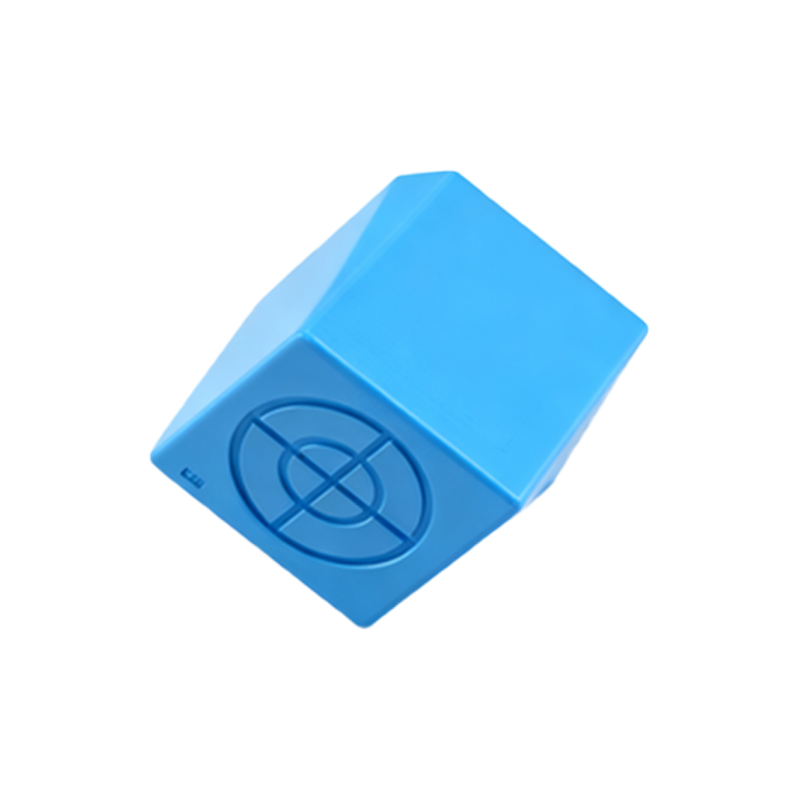
Assuming a stable and correct power supply is confirmed, the investigation must focus on the proximity sensor. Modern passive infrared (PIR), microwave, ultrasonic, or dual-technology sensors are sophisticated devices with configurable parameters and potential failure points. Start by verifying the sensor's basic settings. The "LUX" or daylight threshold setting might be adjusted too high, causing the sensor to believe ambient light is sufficient and thus inhibiting the output signal. Temporarily set this to its minimum or test mode to rule it out. Next, examine the sensing range and delay time settings. An excessively short range or an unusually long delay time could create the perception of non-operation. The sensor lens must be clean and unobstructed; accumulated dust, grease, or physical barriers can severely attenuate the detection signal.
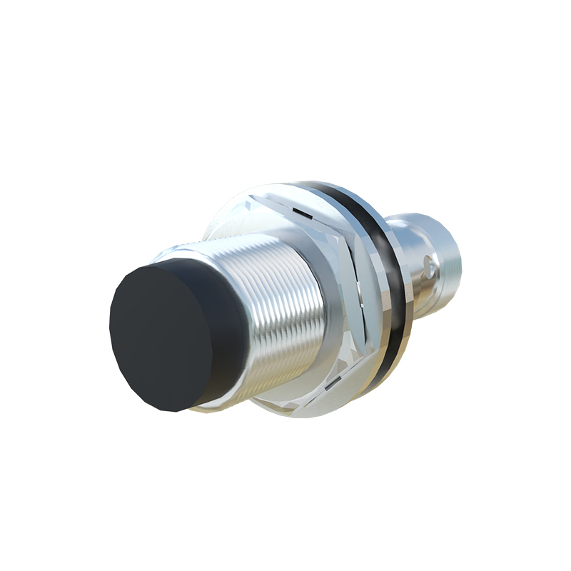
Sensor failure can be internal. Using the multimeter, check for a switching output signal (voltage change or contact closure) at the sensor's load control wires when motion is simulated within its field of view. No change in state suggests a faulty sensor. Environmental factors also play a critical role. Extreme temperatures beyond the sensor's specified operating range can cause malfunction. Electrical noise from nearby variable frequency drives (VFDs), heavy motors, or radio transmitters can interfere with the sensor's sensitive electronics, leading to erratic behavior or lock-up. In such cases, proper shielding, filtering, or relocation of the sensor may be necessary.
If the sensor is confirmed to be providing a correct output signal, the fault likely lies in the load control path or the luminaire. The sensor typically operates a relay or solid-state switch to complete the circuit to the light. This switching component can fail. Bypass the sensor temporarily by carefully connecting the load directly to the line power (following strict lockout-tagout procedures). If the light illuminates, the switching component within the sensor or an external relay/contactor is defective. If the light still does not turn on, the problem is isolated to the wiring between the sensor and the fixture, or the fixture itself.
Finally, diagnose the luminaire. For LED fixtures, which are now predominant, internal drivers or constant current sources can fail. Check for visible signs of damage, such as bulging capacitors or burnt components. Even if the driver is functional, one or multiple LED arrays within the module may have failed open-circuit. For fluorescent fixtures with sensor ballasts, the ballast itself could be faulty, or the lamps may have reached end-of-life. A direct voltage measurement at the luminaire's input terminals during the time the sensor is supposed to be activated will conclusively determine if power is reaching the fixture.
In summary, troubleshooting a non-illuminating proximity sensor light demands a logical, step-by-step methodology. Begin with power source verification, proceed to sensor configuration and output testing, consider environmental interference, and finally, examine the load switching mechanism and the luminaire. Documenting findings and solutions not only resolves the immediate issue but also builds a valuable knowledge base for preventing future occurrences and optimizing system reliability. Regular preventive maintenance, including cleaning sensor lenses, checking connections, and verifying settings, is paramount to ensuring these automated lighting systems perform as intended.