Proximity sensors are critical components in industrial automation, providing non-contact detection of metallic or non-metallic objects. An open circuit failure, often referred to as a "break" or "disconnection" in the sensor's wiring or internal circuitry, can lead to unexpected machine downtime and production losses. As an experienced electrical engineer, I will guide you through a systematic approach to debug and resolve proximity sensor open circuit issues, ensuring minimal disruption to operations.
First, understand the common symptoms of an open circuit failure. The sensor may stop detecting objects entirely, exhibit intermittent operation, or cause the connected PLC (Programmable Logic Controller) to register a fault. Before assuming the sensor is faulty, perform a visual inspection. Check the sensor housing for physical damage, corrosion, or loose connections. Examine the cable for cuts, abrasions, or pinch points, especially near cable glands or moving parts. Verify that the connector is securely attached and free from moisture or contaminants.
Next, use a multimeter to conduct electrical tests. For a 3-wire DC proximity sensor (typically with brown, blue, and black wires), follow these steps:
1. Power Off: Ensure the system is de-energized to prevent electrical hazards.
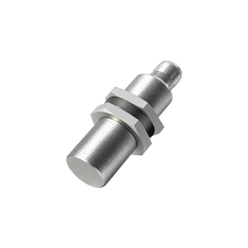
2. Continuity Check: Set the multimeter to continuity or resistance mode. Test between the brown wire (positive) and blue wire (negative). A healthy sensor should show some resistance (not open circuit). If the reading is infinite (OL), there is likely an internal break.
3. Output Test: Reconnect power. Measure voltage between the black wire (output) and blue wire (negative). When an object is within sensing range, the output should switch (e.g., from 0V to 24V for PNP type). No change indicates a potential open circuit.
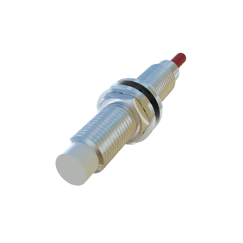
For 2-wire AC/DC sensors, check continuity between the two wires with power off, and monitor current draw during operation.
If the sensor itself tests fine, inspect the wiring and connections. Open circuits often occur at terminal blocks, junction boxes, or splices. Use the multimeter to test continuity along the entire cable path from the sensor to the controller. Look for loose screws, oxidized contacts, or broken strands. In harsh environments, vibration or thermal cycling can weaken connections over time.
Consider external factors that mimic open circuit failures. Electrical noise from nearby motors or frequency drives can interfere with sensor signals. Ensure proper shielding and grounding of cables. Additionally, verify the sensing distance and alignment; misalignment may cause the sensor to appear faulty. Check the target material and size—some sensors require specific metals or minimum dimensions for reliable detection.
For programmable or intelligent sensors, use diagnostic tools. Many modern sensors have LED indicators or communication interfaces (e.g., IO-Link) that provide detailed status information. Consult the manufacturer's manual to interpret error codes. If the sensor is network-connected, use software to monitor its parameters and detect communication drops.
If debugging confirms an internal open circuit, replace the sensor. Choose a model with appropriate specifications (e.g., sensing range, output type, environmental rating). After installation, recalibrate if necessary and document the failure for preventive maintenance. Regularly schedule inspections to avoid recurrence.
In summary, troubleshooting proximity sensor open circuits requires a methodical process: visual inspection, electrical testing, wiring checks, and environmental assessment. By following these steps, engineers can quickly restore functionality and enhance system reliability. Always prioritize safety by locking out power during physical inspections and adhere to industry standards such as IEC 60947-5-2 for sensor performance.