In industrial automation and control systems, proximity switch sensors are indispensable components for non-contact detection of objects. Their primary function is to sense the presence or absence of a target within a specific range without physical contact. However, the raw signal generated by these sensors is often not directly compatible with the broader control system, necessitating a crucial process: signal conversion. This article delves into the principles, methods, and practical considerations of converting proximity sensor signals into usable control signals.
The core operation of a proximity sensor involves generating an electrical signal—typically a change in voltage, current, or oscillation state—when a metallic or sometimes non-metallic target enters its sensing field. Common types include inductive (for metals), capacitive (for various materials including liquids), and ultrasonic sensors. Each type produces a distinct raw output. For instance, a standard DC 3-wire inductive proximity switch might provide a switching output, either NPN (sinking) or PNP (sourcing), where the signal wire switches between 0V (or supply voltage) and the supply voltage (or 0V) relative to the common wire.
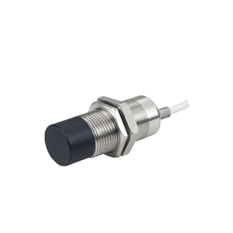
The need for signal conversion arises from several system requirements. The control system's logic level (e.g., 24VDC PLC input, 5VDC microcontroller input) may differ from the sensor's output level. Long-distance transmission can attenuate signals, requiring conversion to a more robust format like a 4-20mA current loop, which is immune to voltage drop over wires. In noisy industrial environments, converting to a differential signal (like RS-485) enhances noise immunity. Furthermore, some applications require analog representation of distance (not just on/off), or the interfacing of different sensor output types (NPN vs. PNP) with a single controller.
The conversion methodologies are broadly categorized into digital and analog signal conditioning.
For digital (on/off) sensors, conversion often involves level shifting and isolation. A simple resistive divider network can scale down a 24V sensor signal to 5V for a microcontroller. Optocouplers or relay modules provide galvanic isolation, protecting sensitive control electronics from voltage spikes or ground loops present on the sensor side. Solid-state relays (SSRs) or interface modules (like PLC digital input modules) are also common conversion points, standardizing various field device signals to the controller's internal logic voltage.
For analog-output or analog-required applications, conversion is more complex. Some proximity sensors have built-in analog outputs (0-10V or 4-20mA) proportional to the distance to the target. If only a digital sensor is available, a frequency-based method can sometimes be employed, where the distance affects the oscillation frequency, which is then converted to a voltage by a frequency-to-voltage converter (F/V converter). The 4-20mA current loop is a cornerstone in process control. A transmitter circuit converts the sensor's signal into a proportional current. This current signal is highly resistant to electrical noise and voltage drop, making it ideal for long runs. At the controller end, a precision resistor converts the current back to a voltage for measurement.
Key practical considerations during signal conversion include power supply compatibility, ensuring the sensor and conversion circuitry have clean, stable power, often with protection against reverse polarity and transients. Wiring practices are critical; shielded cables are recommended for analog signals, with proper grounding to avoid ground loops. For fast-moving targets, the response time of both the sensor and the conversion circuit must be sufficiently high to not miss detection events. Environmental factors like temperature, humidity, and vibration can affect the stability of conversion components, necessitating the selection of industrial-grade parts.
In modern systems, intelligent signal converters or conditioners offer programmable features. They can scale analog ranges, apply filters to smooth noisy signals, set trigger thresholds, and provide diagnostic information. These devices simplify integration and enhance system reliability.
In conclusion, signal conversion is the critical link that transforms the raw detection event of a proximity switch into a robust, standardized language that programmable logic controllers (PLCs), distributed control systems (DCS), and other industrial controllers can understand and act upon. A proper understanding of sensor output characteristics, system requirements, and conversion techniques is essential for designing reliable, accurate, and maintainable automation systems. By carefully selecting and implementing the appropriate signal conversion strategy, engineers ensure seamless communication between the physical sensing layer and the digital control layer, enabling precise and efficient automated operations.