Proximity sensors, often referred to as "prox switches" or proximity switches, are indispensable components in modern industrial automation. They detect the presence or absence of an object without physical contact, using electromagnetic fields, light, or sound. Correct wiring is paramount for reliable operation, safety, and system integrity. This guide provides a comprehensive, step-by-step approach to wiring common types of proximity sensors, focusing on DC 3-wire and AC 2-wire configurations prevalent in control panels and machinery.
Understanding the Fundamentals
Before handling any wires, it's crucial to understand the sensor's specifications. Always consult the manufacturer's datasheet. Key parameters include:
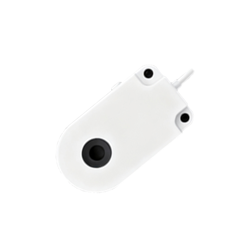
Operating Voltage: Typically 10-30V DC or 90-250V AC.

Output Type: NPN (sinking) or PNP (sourcing) for DC sensors; this defines the current flow path.
Output Configuration: Normally Open (NO) or Normally Closed (NC).
Wiring Diagram: The definitive guide, usually printed on the sensor body or in its documentation.
Safety First!
1. Lock Out, Tag Out (LOTO): Ensure all power sources to the control panel or machine are disconnected, locked, and tagged before beginning any work.
2. Verify Voltage: Use a multimeter to confirm the power is off at the connection points.
3. Use Proper Tools: Employ insulated screwdrivers, wire strippers, and crimping tools.
Wiring a 3-Wire DC Proximity Sensor
This is the most common type. The three wires are usually color-coded: Brown (positive), Blue (negative/neutral), and Black (output signal). Colors may vary; always verify.
1. Identify the Wires: Brown connects to the positive DC supply voltage (e.g., +24V). Blue connects to the DC common or 0V. Black is the switched output wire.
2. NPN vs. PNP Connection:
NPN (Sinking): The Black output wire acts as a switch to ground (0V). When the sensor detects an object, it connects the Black wire to the Blue wire (0V). The load (e.g., a PLC input, relay coil) is connected between the positive supply (+24V) and the Black wire. Current sinks into the sensor.
PNP (Sourcing): The Black output wire acts as a switch to the positive supply. When activated, it connects the Black wire to the Brown wire (+24V). The load is connected between the Black wire and the common (0V). Current sources from the sensor.
3. Connect the Load: Connect one side of your load (PLC input module, relay, indicator lamp) to the Black output wire. Connect the other side of the load to the opposite supply rail based on the sensor type (PNP: to 0V; NPN: to +24V).
4. Example for a PNP Sensor: Brown → +24V DC; Blue → 0V DC; Black → Load → 0V DC.
Wiring a 2-Wire AC Proximity Sensor
These sensors are simpler, with two wires, typically Brown and Blue. They are connected in series with the load and the AC power supply, much like a traditional switch.
1. Identify Wires: One wire (often Brown) connects to the AC Line (Hot). The other wire (often Blue) connects to one side of the load.
2. Complete the Circuit: The other side of the load is then connected to the AC Neutral.
3. Important Consideration: 2-wire sensors have a small leakage current even when "off." This can sometimes cause neon lamps or sensitive PLC inputs to remain active. A bypass resistor may be required per the datasheet.
Wiring a 4-Wire DC Sensor (Dual Output)
These sensors have two output wires (e.g., Black and White), providing both NO and NC functions from the same unit. The Brown and Blue wires are connected to power as described above. The Black and White wires are connected to separate loads, allowing one circuit to close and another to open upon detection.
Best Practices and Troubleshooting Tips
Use Shielded Cable: For long runs or electrically noisy environments, use shielded cable to prevent electromagnetic interference (EMI). Connect the shield to ground at the controller end only.
Secure Connections: Use ferrules on stranded wires for clean, secure terminations in screw-clamp terminals.
Check Indicator LED: Most sensors have an