Proximity sensors are fundamental components in modern automation, robotics, and countless industrial applications. Their primary function is to detect the presence or absence of an object without physical contact. While the sensing technology—be it inductive, capacitive, photoelectric, or ultrasonic—often garners attention, the electrical signal output, particularly the signal voltage, is the critical language through which the sensor communicates with the wider control system. Understanding proximity sensor signal voltage is essential for proper selection, integration, and troubleshooting.
At its core, the signal voltage is the electrical representation of the sensor's detection state. For a standard digital (on/off) proximity sensor, this typically manifests as two distinct voltage levels. When no target is present, the sensor is in its normal state, outputting either a high voltage (e.g., 24V DC) or a low voltage (e.g., 0V DC), depending on its configuration. Upon detecting a target within its specified sensing range, the output switches to the opposite state. This clean, binary signal is the workhorse of discrete event control, telling a Programmable Logic Controller (PLC), counter, or relay precisely when an event has occurred.
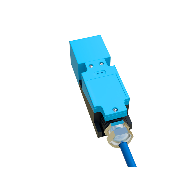
The nominal operating voltage of the sensor's power supply directly dictates the range of its output signal voltage. Common DC supply voltages include 10-30V DC or 12-24V DC, with 24V DC being an industrial standard. A sensor rated for 10-30V DC will typically output a signal voltage very close to its actual supply voltage when in the "on" state. For instance, if powered by 24V DC, the high signal might be around 23.5V, accounting for a small internal voltage drop. The "off" state voltage should be very close to 0V. It is crucial to match both the sensor's supply voltage and its output type (NPN vs. PNP, sourcing vs. sinking) with the input requirements of the connected control device. A mismatch here is a primary cause of system failure.
Signal voltage is not always a perfect square wave. Real-world factors can affect its quality and timing. Load current is a key consideration. Every sensor has a maximum switching capacity (e.g., 100mA). Exceeding this by connecting too large a load can cause the output voltage to sag when active, potentially failing to reach the logic "high" threshold of the receiving device. Conversely, the leakage current in the "off" state, though small (typically microamps), can generate a residual voltage across a high-impedance load, which might be misinterpreted as a "high" signal. Understanding the load specifications prevents such issues.
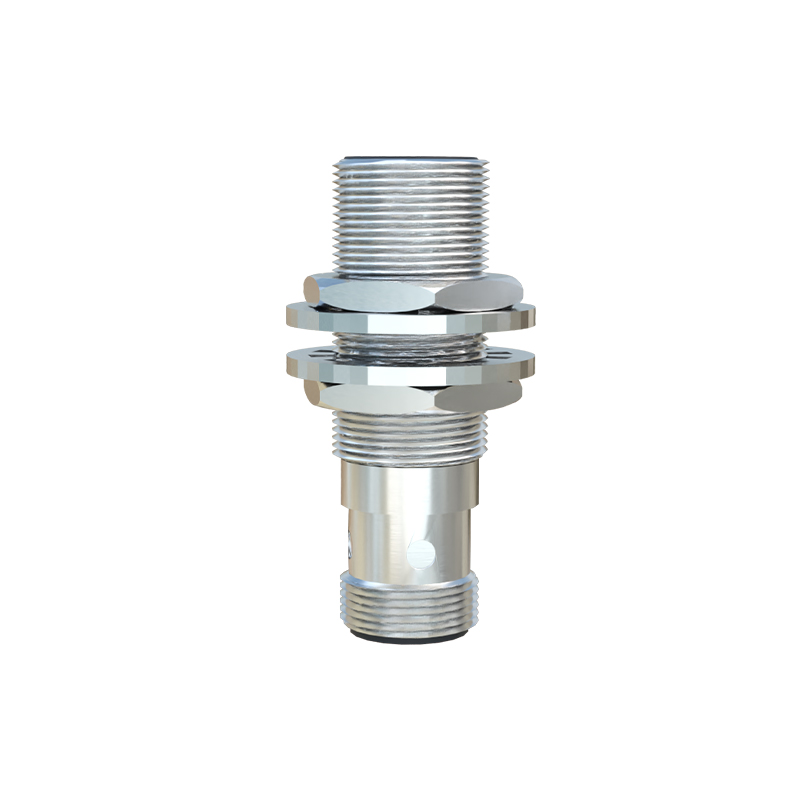
Response time, another critical parameter, is intrinsically linked to how quickly the signal voltage can transition between states. A sensor with a 1ms response time can switch its output from 0V to 24V (or vice versa) within that millisecond. In high-speed counting or positioning applications, a slow voltage transition can lead to missed counts or inaccurate timing. Furthermore, electrical noise from motors, drives, or welding equipment can induce voltage spikes or fluctuations on the signal line, corrupting the clean digital signal. Proper wiring practices—using shielded cables, separating signal lines from power lines, and ensuring good grounding—are vital to maintain signal voltage integrity.
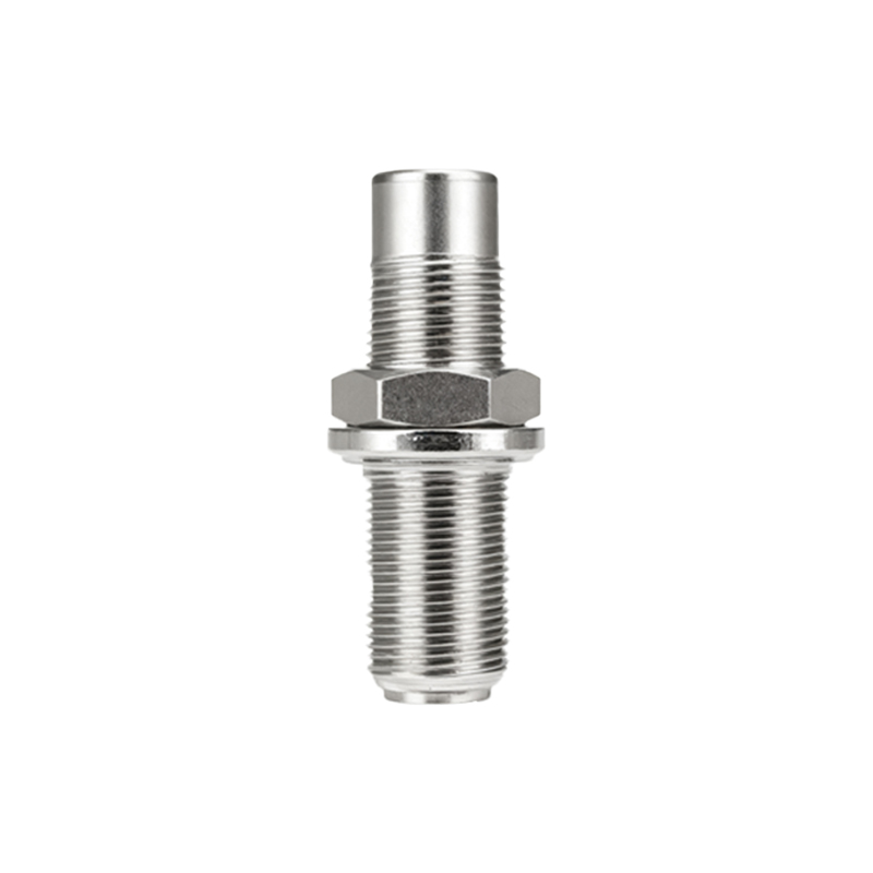
Troubleshooting often begins with a multimeter. If a sensor appears non-functional, measuring the voltage between the output wire and the common (0V) wire while triggering the sensor is the first diagnostic step. A reading that does not change, or one that shows an intermediate, unstable voltage (e.g., 12V instead of a solid 0V or 24V), points to a problem. This could be a faulty sensor, an incorrect load, a wiring issue, or severe electrical interference. Checking the voltage under load, rather than with the sensor disconnected, provides the most accurate picture.
In summary, the signal voltage is the definitive output of a proximity sensor. Its defined levels, transition speed, and stability under load are the metrics that determine successful integration into a control system. Engineers and technicians must move beyond simply knowing that a sensor "clicks on" and instead focus on the precise electrical characteristics of that "click." By paying close attention to supply voltage compatibility, output configuration, load specifications, and environmental noise, one can ensure that the silent, voltage-based language of the proximity sensor is accurately heard and acted upon by the controlling intelligence of the machine.