In the realm of industrial automation and electrical engineering, proximity sensors are indispensable components for non-contact detection of objects. Among the various wires in their connection cables, the red wire often becomes a focal point for installation and troubleshooting. This article delves into the standard functions, wiring conventions, and critical considerations surrounding the red wire in common proximity sensor configurations.
Typically, in a standard 3-wire DC proximity sensor, the wire color coding follows a widely accepted international convention, though manufacturers' documentation should always be the primary reference. In this scheme, the red wire is almost universally designated as the positive supply voltage line (+V or V+). It is the conduit through which the sensor receives the power necessary for its internal circuitry, oscillator, and output switching components. For sensors operating on DC voltages, commonly 10-30V DC, this red wire must be connected to the positive terminal of the power supply. The reliability of the entire sensing loop hinges on this connection's integrity.
The companion wires are usually brown (for positive) in some regions, but more consistently, black (for output signal) and blue (for negative supply or 0V). It is crucial to understand that the red wire's role is purely for powering the sensor's electronics. It does not directly carry the switched load current to the controlled device, such as a PLC input or a relay coil. That function is managed by the output wire (often black). The internal solid-state switch (PNP or NPN) connects this output wire to either the positive supply (if PNP/sourcing) or the negative supply (if NPN/sinking), but the red wire remains the dedicated power inlet.
Wiring the red wire incorrectly can lead to several immediate issues. Connecting it to the negative terminal while the blue wire is on positive will reverse the polarity. Most modern DC sensors are equipped with reverse polarity protection, preventing catastrophic failure, but the sensor will simply not operate. A more subtle error involves confusing the red wire with the output wire. If the red wire is connected to a PLC digital input instead of the black wire, the PLC input would be constantly energized because it is directly tied to the positive supply, rendering the sensor's detection capability meaningless. Always verify the wiring diagram on the sensor's nameplate or datasheet.
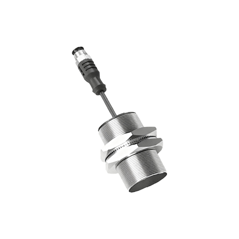
For 2-wire AC/DC sensors, the color coding is different, often using brown and blue. In these models, there is no dedicated red wire for separate power, as the two wires carry both the supply power and the load current in series. Therefore, encountering a red wire is a strong indicator of a 3-wire or 4-wire DC sensor. In more complex 4-wire sensors, which may have two separate outputs (e.g., one Normally Open and one Normally Closed), the red wire retains its primary role as the V+ line, while additional wires, like white or gray, are used for the second output signal.
Best practices for handling the red wire start with a disciplined installation routine. First, always de-energize the circuit before making connections. Use appropriate tools to strip and secure the wire in the terminal block, ensuring a firm, corrosion-free connection to prevent voltage drop. Implement proper wire management, such as ducting or sleeving, to protect the cable from mechanical abrasion, especially near moving parts. For maintenance, having the sensor's manual or a clear system wiring schematic is invaluable for quickly verifying the red wire's path.
Troubleshooting often involves checking the voltage on the red wire. With a multimeter, measure the voltage between the red wire (at the sensor's connector) and the blue wire (or a known ground). It should read within the specified sensor range (e.g., 24V DC ±10%). An absent or low voltage here points to a problem upstream—a blown fuse, a tripped circuit breaker, or a faulty power supply. If voltage is present but the sensor is inactive, the issue may lie in the sensor itself or the load connection on the output wire.
In conclusion, the red wire in a proximity sensor is its lifeline to electrical power. Its consistent designation as the V+ line across much of the industry provides a helpful benchmark for engineers and technicians. However, this consistency should never breed complacency. A meticulous approach—prioritizing manufacturer documentation, adhering to safe wiring practices, and methodically verifying connections—ensures that this critical red wire fulfills its function reliably, supporting the seamless and efficient operation of automated systems. Remember, in control systems, correctness in the smallest detail, like a single wire, is what guarantees overall performance and safety.