Proximity sensors are indispensable components in modern industrial automation, offering non-contact detection of metallic or non-metallic objects. Correct wiring is fundamental to ensuring their reliable operation, safety, and longevity within a control system. This guide provides a comprehensive, step-by-step approach to wiring common types of proximity switches, adhering to standard industrial practices.
Understanding Proximity Sensor Types and Outputs
Before connecting any wires, identifying the sensor type and its output configuration is crucial. The two primary categories are:
1. Inductive Proximity Sensors: Detect ferrous and non-ferrous metals. They are typically housed in a metallic barrel.
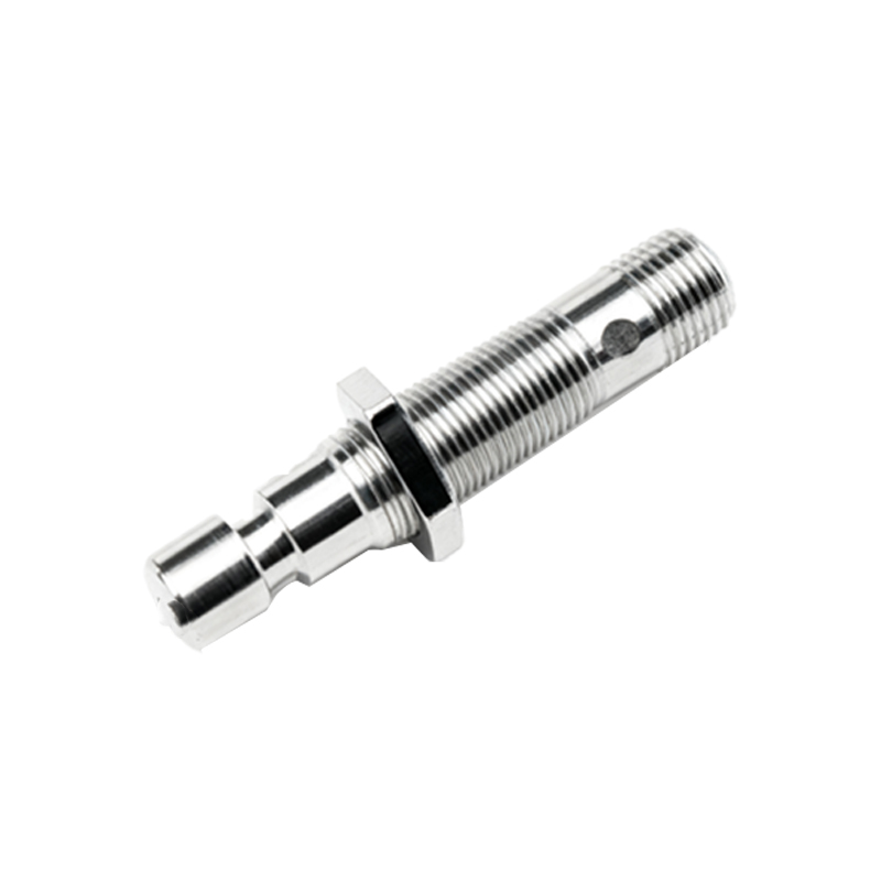
2. Capacitive Proximity Sensors: Detect a wider range of materials, including metals, plastics, liquids, and granular substances.
Regarding electrical output, the most common configurations are:
2-Wire DC Sensors: These act like a switch in series with the power supply and load. They are simpler but have a higher residual current (leakage) when "off" and a voltage drop when "on."
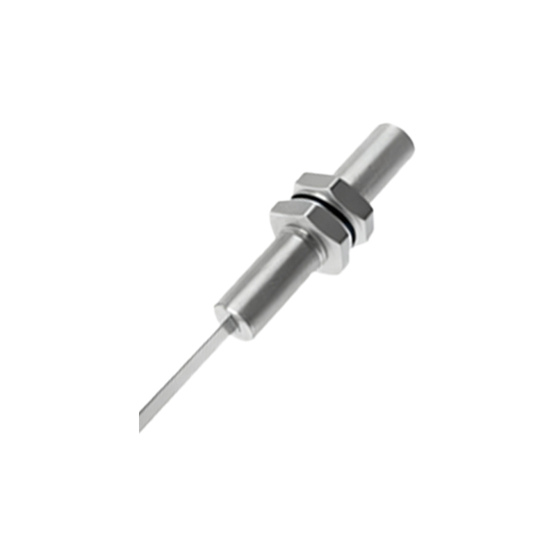
3-Wire DC Sensors: The most prevalent type. They have separate wires for power supply positive (brown or red), power supply negative (blue or black), and the switching output signal (black, white, or blue). Outputs can be NPN (sinking) or PNP (sourcing).
4-Wire DC Sensors: These often provide both a Normally Open (NO) and a Normally Closed (NC) output from the same device.
AC Sensors: Usually 2-wire or 4-wire configurations operating on standard line voltage (e.g., 120VAC, 240VAC).

Safety First: Essential Pre-Wiring Checklist
Disconnect Power: Always lock out and tag out (LOTO) the main power source to the control panel or circuit.
Verify Specifications: Consult the sensor's datasheet for its operating voltage range, output type (NPN/PNP, NO/NC), current rating, and wiring diagram.
Prepare Tools: Use appropriate wire strippers, crimping tools, screwdrivers, and a digital multimeter (DMM).
Select Correct Cable: Use shielded cable in electrically noisy environments. Ensure wire gauge is suitable for the current load.
Step-by-Step Wiring Procedure for a 3-Wire DC Sensor
Let's focus on the ubiquitous 3-wire DC sensor, as the principles apply broadly.
Step 1: Identify the Wires
Standard color coding (IEC) is common but not universal. Always check the sensor's label or datasheet.
Brown (or Red): Connected to the positive DC supply voltage (+V).
Blue (or Black): Connected to the negative DC supply voltage (0V or Common).
Black (or White/Blue): This is the switched output signal wire.
Step 2: Determine the Output Logic (NPN vs. PNP)
This is critical for compatibility with your PLC or controller input card.
PNP (Sourcing) Sensor: The output wire switches the positive voltage to the load. When activated, the output wire becomes "high" (e.g., +24V). The load (e.g., PLC input) is connected between the sensor output and common (0V).
NPN (Sinking) Sensor: The output wire switches the negative or 0V connection to the load. When activated, the output wire goes "low" (0V). The load is connected between the positive supply (+V) and the sensor output.
Step 3: Connect Power Supply Wires
1. Connect the sensor's brown wire to the positive terminal of your DC power supply (e.g., +24VDC).
2. Connect the sensor's blue wire to the negative/0V terminal of the same DC power supply.
3. Ensure connections are tight and secure.
Step 4: Connect the Output Signal Wire
The connection depends on whether you have a PNP or NPN sensor and what you are connecting it to (e.g., PLC, relay, indicator lamp).
Example: Connecting a PNP Sensor to a PLC Digital Input:
The PLC input card likely requires a connection to "Common" (0V) to complete the circuit.
Connect the sensor's black (output) wire directly to the designated PLC input terminal (e.g., I0.0).
The corresponding common terminal for that input group on the PLC card must be connected to 0V (DC common).