Proximity sensors are widely used in industrial automation for detecting the presence or absence of objects without physical contact. Proper wiring is crucial for accurate and reliable operation in experimental setups. This article provides a comprehensive guide to wiring methods for inductive, capacitive, and ultrasonic proximity sensors, focusing on practical steps and safety considerations.
First, ensure all power sources are disconnected before starting any wiring work. Gather necessary tools: a multimeter, screwdrivers, insulated wires, and appropriate connectors. Check the sensor datasheet for specifications such as operating voltage, output type (PNP or NNP), and sensing range. Most proximity sensors have three wires: brown (positive), blue (negative), and black (output). For DC sensors, connect the brown wire to the positive terminal of the power supply (typically 12-24V DC) and the blue wire to the negative terminal. The black wire links to the load (e.g., PLC input or relay). In PNP sensors, the output provides positive voltage when activated; in NPN sensors, it sinks current to ground.
For inductive sensors, commonly used for metal detection, mount the sensor securely to avoid vibration interference. Maintain a clearance of at least twice the sensor’s diameter from nearby metal objects to prevent false triggers. Test the wiring by applying power and bringing a target object within the sensing range. Use a multimeter to verify output voltage changes. If the sensor fails to respond, recheck connections and ensure the target material is compatible (e.g., ferrous metals for standard inductive sensors).
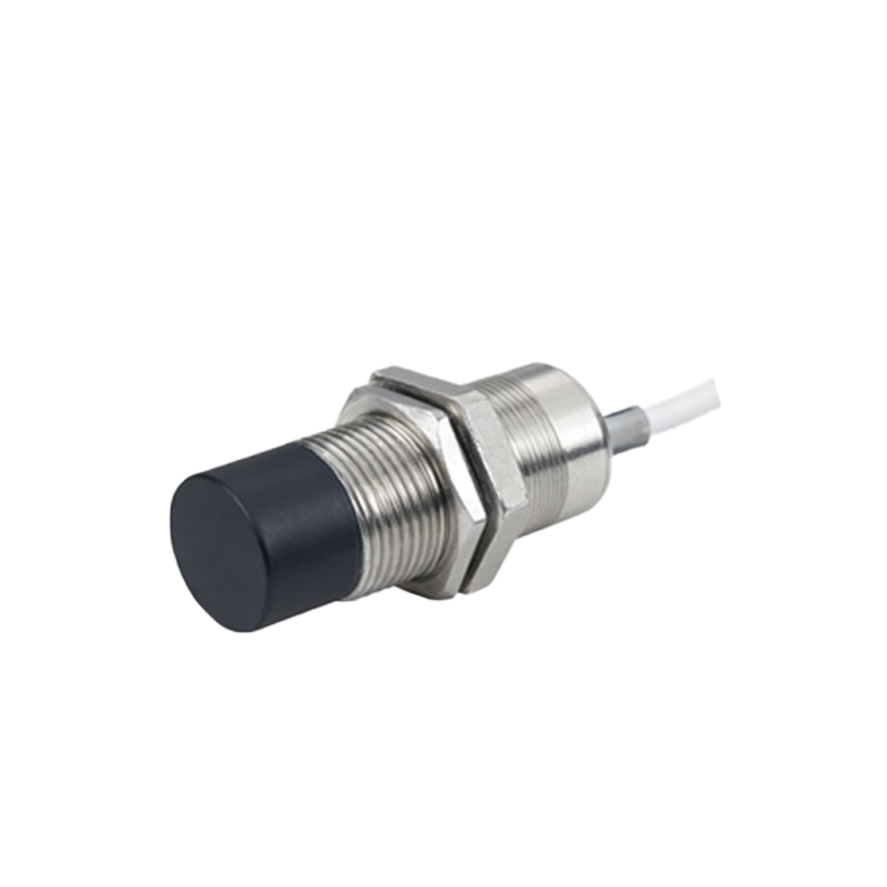
Capacitive sensors, suitable for non-metallic materials like liquids or plastics, require careful calibration due to sensitivity to environmental factors. Wire them similarly to inductive sensors, but adjust the sensitivity potentiometer after installation. Avoid placing capacitive sensors near high-humidity areas or conductive surfaces to minimize drift. In experiments involving containers, mount the sensor externally to detect level changes without direct contact.
Ultrasonic sensors use sound waves for detection and often have four wires: power (brown and blue), output (black), and a configuration wire (white). Connect power as described, and use the output wire based on required logic (e.e., normally open or closed). Calibrate the sensing distance via built-in potentiometers or teach-in functions. Ensure the target surface is perpendicular to the sensor for optimal reflection, and avoid obstacles in the sound path.
In complex setups, integrate multiple sensors with a PLC. Use shielded cables for long runs to reduce electrical noise, and ground the shield at one end. For AC-powered sensors, follow local electrical codes and include fuses for overload protection. Always document wiring diagrams for future reference. Troubleshoot common issues like no output or erratic behavior by checking power supply stability, wire integrity, and environmental interferences (e.e., temperature extremes or electromagnetic fields).
Regular maintenance includes cleaning sensor faces and verifying connections. By following these methods, engineers can ensure precise and safe proximity sensor operation in experimental environments, leading to reliable data and system performance.