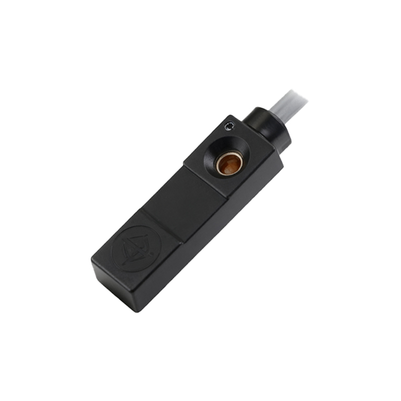
In the realm of industrial automation, proximity switch sensors are indispensable components for non-contact detection of metallic and, in some cases, non-metallic objects. A critical parameter that often requires careful consideration during system design and troubleshooting is the sensor's output current. This article delves into the technical aspects of proximity sensor output current, its specifications, influencing factors, and practical implications for reliable system operation.
At its core, the output current of a proximity sensor refers to the maximum continuous current its switching element (typically a solid-state transistor) can safely handle when in the "ON" state. This is fundamentally different from the sensor's operating current or supply current. The output current rating, usually denoted as I_load or I_out in datasheets, specifies the limit for the load connected to the sensor's output terminal. Common output configurations include PNP (sourcing), NPN (sinking), and relay outputs, each with distinct current-handling characteristics. For standard 2-wire and 3-wire DC sensors, output current ratings typically range from 100mA to 500mA, though heavy-duty models can exceed 1A. AC sensors often incorporate relay outputs capable of handling several amperes.
Several key factors directly impact the performance and longevity related to output current. First is the load type. Resistive loads, like indicator lamps, are straightforward. Inductive loads, such as solenoids, relays, or contactor coils, present a challenge due to inrush currents and voltage transients generated when the circuit is interrupted. For inductive loads, it is a standard practice to derate the sensor's maximum output current, often by 20-30%, or to employ protective circuits like flyback diodes for DC loads or RC snubbers for AC loads to suppress voltage spikes. Secondly, ambient temperature plays a significant role. Semiconductor-based outputs have a negative temperature coefficient; their maximum permissible output current decreases as the ambient temperature rises. Datasheets provide derating curves that must be consulted for applications in high-temperature environments. Ignoring this can lead to thermal overload and premature failure.
The relationship between output current and voltage drop is also crucial. When the output transistor is conducting, it does not act as a perfect short circuit. It exhibits a small internal resistance, leading to a voltage drop between the supply voltage and the voltage actually delivered to the load. This voltage drop, specified as V_sat (saturation voltage) for transistor outputs, increases slightly with the load current. For a sensor with a 24VDC supply and a V_sat of 2V at 200mA, the load would receive approximately 22V. This must be verified to ensure the connected device (e.g., a PLC input module or a relay) receives sufficient voltage to operate reliably. Exceeding the maximum output current can cause excessive heating within the sensor, elevating V_sat and potentially creating a scenario where the load voltage falls below its operational threshold, even if the current is within an absolute maximum limit.
In practical application and circuit design, selecting a sensor with an appropriate output current rating is paramount. The golden rule is to choose a sensor whose maximum continuous output current exceeds the steady-state current draw of the load by a safe margin, typically 20%. This margin accounts for minor current surges and provides a buffer for long-term reliability. For example, a relay coil drawing 150mA should be driven by a sensor rated for at least 180mA. Furthermore, when connecting to programmable logic controller (PLC) digital inputs, one must ensure the sensor's output current capability is compatible with the input's required operating current. Some high-density PLC modules have low input current requirements (e.g., 5-10mA), making them compatible with virtually all standard sensors. However, the sensor's leakage current in the "OFF" state must also be considered to prevent false triggering of sensitive inputs.
Troubleshooting issues often circle back to output current. Symptoms of an overloaded output include the sensor failing to turn on the load consistently, excessive heat generation from the sensor housing, or complete sensor failure. Using a digital multimeter to measure the actual load current under operating conditions is a fundamental diagnostic step. If the measured current approaches or exceeds the sensor's rating, the solution may involve switching to a sensor with a higher current capacity, inserting an intermediate relay to handle the heavy load (using the sensor to drive the relay coil), or re-evaluating the load itself for faults like shorted windings.
In conclusion, a thorough understanding of proximity switch sensor output current is not merely an academic exercise but a practical necessity for robust system design. By carefully matching the sensor's output specifications to the load requirements, considering environmental conditions, and implementing proper protective measures for challenging loads, engineers can ensure high reliability, extended service life, and minimized downtime in automated industrial systems. Always prioritize consulting the manufacturer's datasheet,