In the realm of industrial automation, proximity sensors are indispensable components for non-contact object detection. Among the various configurations, Normally Open (NO) proximity sensors represent a fundamental and widely utilized output type. This article delves into the operational principles, electrical characteristics, and practical application considerations of NO proximity sensor outputs, providing a comprehensive guide for engineers and technicians.
At its core, a Normally Open (NO) proximity sensor is defined by the state of its output switching circuit when no target is within its sensing range. In this undisturbed state, the output circuit is open, meaning there is no electrical continuity between the output terminal and the common terminal (typically the power supply negative or positive, depending on the sensor's sinking or sourcing configuration). No current flows through the load connected to the sensor. The term "open" is analogous to a switch that is off. When a valid target enters the sensor's specified detection field, the internal electronic circuitry is triggered. This action closes the output switching element (such as a transistor or solid-state relay), completing the circuit. Current can then flow from the power supply, through the sensor's output, to the connected load (e.g., a PLC input, relay coil, or indicator lamp), and back to the power supply, thereby activating the load.
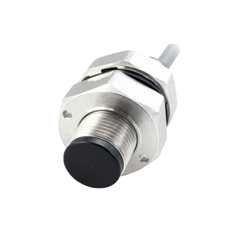
The output stage of modern inductive, capacitive, or photoelectric proximity sensors with NO configuration is predominantly solid-state. The most common types are NPN (sinking) and PNP (sourcing) transistor outputs. For a 3-wire DC sensor with an NPN NO output, the output transistor is off (open) when no target is present. Upon detection, the NPN transistor turns on, connecting the output terminal to the common (usually 0V), allowing current to sink from the load into the sensor. Conversely, a PNP NO output sensor has its output transistor off (open) in the idle state. When activated, the PNP transistor turns on, connecting the output terminal to the positive supply voltage, sourcing current out to the load. It is crucial to match the sensor's output type (NPN/PNP) with the input requirements of the controller or load to ensure proper system operation.
Wiring an NO proximity sensor is straightforward. A typical 3-wire DC sensor requires a DC power supply (commonly 10-30V DC). The brown wire (or +) connects to the positive voltage, the blue wire (or -) to the negative/0V, and the black wire is the NO output signal line. The load is connected between the black output wire and the opposite power supply rail. For an NPN sensor, the load is connected between the output and the positive supply (+V). When the sensor activates, it connects the output to 0V, completing the circuit to ground. For a PNP sensor, the load is connected between the output and 0V. Activation connects the output to +V, completing the circuit to positive.
The choice between NO and its counterpart, Normally Closed (NC), is driven by application logic and safety requirements. NO outputs are intuitive for "presence indicating" functions. For instance, detecting a part on a conveyor to start a process, counting objects as they break a beam, or confirming a cylinder is in the extended position. The logic is simple: target present = output ON = signal high (for PNP) or low (for NPN). This direct correlation often simplifies PLC programming. Furthermore, NO configurations are frequently preferred in safety-monitoring circuits designed to detect wire breaks. In a typical safety loop using NC sensors, a wire break mimics a safe condition. However, with NO sensors wired in series, a wire break will cause the circuit to open, indicating a fault. This "de-energize to trip" philosophy is central to many fail-safe designs.
Several critical parameters must be considered when applying NO proximity sensors. The load current rating of the output must not be exceeded; exceeding it can destroy the internal switching transistor. Similarly, the leakage current in the OFF state, though minimal (typically microamps), must be considered when driving highly sensitive PLC inputs, as it might be misinterpreted as an ON signal. In such cases, a bleeder resistor may be necessary. The switching frequency or response time of the sensor must be capable of tracking the speed of the target objects. Environmental factors like temperature, humidity, and electrical noise can also affect performance. Proper shielding, grounding, and the use of surge suppressors for inductive loads are essential for reliable long-term operation.
In conclusion, the Normally Open output configuration provides a logical, reliable, and widely compatible interface for detecting the presence of objects in automated systems. Understanding its electrical behavior—open circuit at rest, closed circuit when activated—is fundamental. By carefully selecting the correct output type (NPN vs. PNP), respecting electrical specifications,