In the realm of industrial automation and motor control, accurately determining motor speed is paramount for operational efficiency, safety, and process optimization. Proximity sensors, particularly inductive and capacitive types, have become a cornerstone technology for this non-contact measurement task. This article delves into the principles, methodologies, and practical considerations of using proximity sensors to measure motor rotational speed.
The fundamental principle is elegantly simple. A proximity sensor is mounted near a rotating component of the motor, typically the shaft, a gear, or a specially designed target such as a keyway or a bolt head on a coupling. As the motor rotates, each target (like a gear tooth or a bolt) passes by the sensor's active face. The sensor detects the presence or absence of the metallic or material target, generating a digital pulse for each pass. This stream of pulses forms a frequency signal directly proportional to the rotational speed.
The core calculation for determining Revolutions Per Minute (RPM) is straightforward: RPM = (Frequency of Pulses in Hz 60) / Number of Targets per Revolution. For instance, if a gear with 10 teeth is used as the target and the sensor generates a pulse frequency of 200 Hz, the motor speed is (200 60) / 10 = 1200 RPM. The number of targets per revolution is critical; a single target (like one bolt) will generate one pulse per revolution, while a multi-toothed gear provides higher resolution and accuracy, especially at lower speeds.
Several key factors influence the accuracy and reliability of this measurement. First is sensor selection. Inductive proximity sensors are the most common for detecting ferrous metals (steel, iron) on motor shafts or gears. For non-metallic targets or specific applications, capacitive sensors may be employed. The sensor's switching frequency must be rated higher than the maximum expected pulse frequency to avoid missing pulses. A sensor with a 5 kHz switching frequency can reliably measure speeds generating up to 5000 pulses per second.
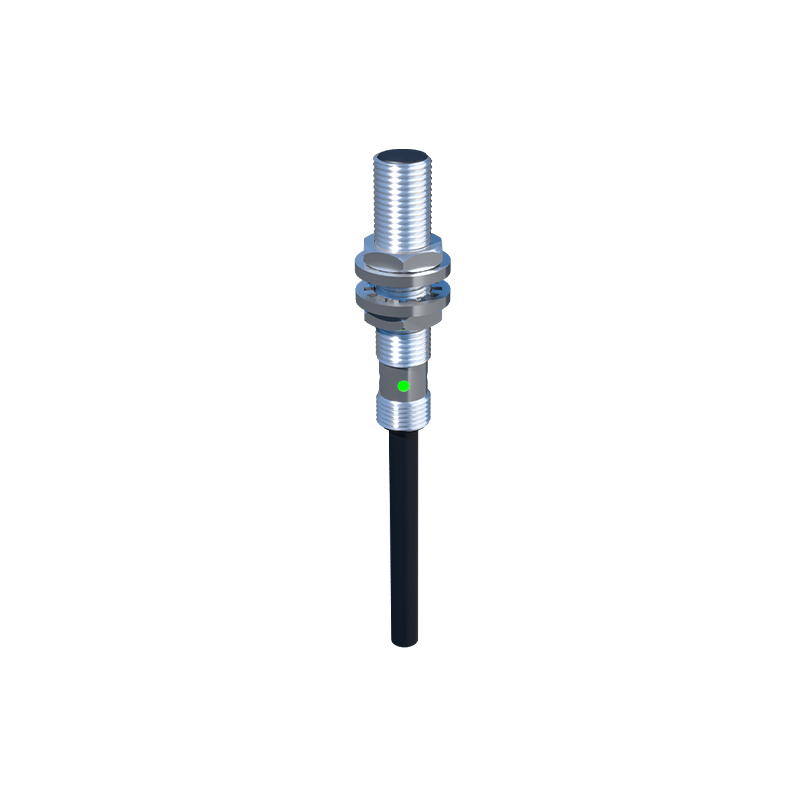
Second is installation and alignment. The sensor must be positioned within its specified sensing range, typically a few millimeters from the target. Proper alignment ensures consistent and strong pulse generation. Vibration and environmental factors like temperature, oil, or coolant must be considered, often necessitating sensors with appropriate IP (Ingress Protection) ratings.
Third is signal conditioning. The raw pulse signal from the sensor may require conditioning. Many modern programmable logic controllers (PLCs) and frequency counters have high-speed counter inputs designed specifically for this purpose. The conditioning involves filtering out electrical noise, which is common in motor control environments, to ensure a clean digital signal for accurate frequency calculation.
Advanced applications often integrate this speed feedback into a control loop. For example, in variable frequency drive (VFD) systems, the pulse signal from a proximity sensor can serve as a feedback signal for closed-loop speed control, allowing the drive to make real-time adjustments to maintain a set RPM despite varying loads. This is crucial in applications like conveyor systems, centrifuges, and machine tool spindles.
When compared to other speed measurement technologies like encoders or tachogenerators, proximity sensor systems offer distinct advantages. They are generally more robust, cost-effective for basic speed monitoring, and easier to install and maintain in harsh industrial environments. Encoders provide vastly higher resolution and directional information but at a higher cost and complexity.
In practice, troubleshooting common issues involves checking the sensor's output with an oscilloscope or a multimeter with frequency capability to verify the pulse signal is present and at the expected frequency. Issues often stem from incorrect sensor-to-target distance, a damaged target, excessive buildup of debris on the sensor face, or electrical interference.
In conclusion, using proximity sensors for motor speed measurement is a highly effective, reliable, and economical method widely adopted in industry. Its success hinges on correct sensor selection based on target material, precise calculation involving pulses per revolution, and careful attention to installation and electrical integration. By mastering these elements, engineers and technicians can ensure precise motor speed monitoring, forming the backbone of efficient and safe automated systems.