Proximity switch sensors are fundamental components in modern industrial automation, providing non-contact detection of metallic and, in some cases, non-metallic objects. Their reliability directly impacts system uptime, product quality, and safety. Therefore, a thorough understanding of calibration principles is paramount for engineers and technicians. Calibration is not merely an initial setup procedure; it is a critical process that ensures the sensor operates within its specified parameters, delivering consistent and accurate switching signals throughout its service life.
The core principle of proximity sensor operation is based on electromagnetic fields. Inductive sensors generate an oscillating electromagnetic field from a coil. When a conductive (typically metallic) target enters this field, eddy currents are induced in the target, which dampens the oscillation amplitude. The sensor's internal circuitry detects this change and triggers a switching action. Capacitive sensors, used for non-metallic materials, create an electrostatic field. The presence of any material with a different dielectric constant than air alters the capacitance of the system, which is then detected. The calibration process essentially fine-tunes the sensor's electronics to respond predictably to these physical changes at a predefined distance—the sensing distance (Sn).
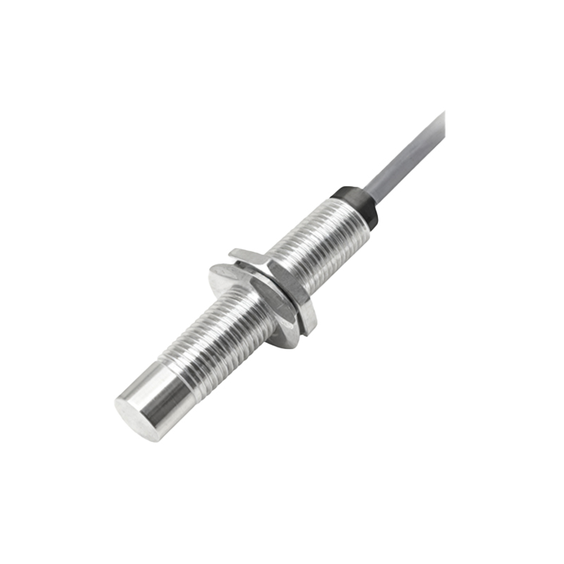
The primary parameter in calibration is setting the operating point, which defines the electrical state of the output (ON or OFF) at a specific target distance. This is intrinsically linked to the concept of hysteresis. Hysteresis is a deliberate, built-in difference between the switch-on point (when the target approaches) and the switch-off point (when the target recedes). It is expressed as a percentage of the nominal sensing distance (e.g., 3-10% for inductive sensors). This feature is crucial for preventing output chatter or oscillation when a target is positioned at the very edge of the sensing range, such as due to machine vibration or minor positional drift. During calibration, the hysteresis value is either factory-set or, in advanced sensors, configurable to suit the application's stability requirements.
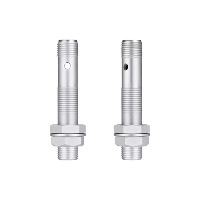
A standard calibration procedure involves several key steps. First, the sensor must be installed in its final operational mounting, as the surrounding metal (flush or non-flush mounting) can influence the electromagnetic field. The recommended target material and shape, as specified in the datasheet (often a square of mild steel of defined thickness), should be used. The target is then moved axially towards the active sensing face. The precise distance at which the output switches state (e.g., from OFF to ON) is recorded as the actual switch-on point. The target is then slowly moved away until the output reverts to its original state; this is the switch-off point. The difference between these two points is the measured hysteresis. The calibration is verified by repeatedly bringing the target to the required operational distance and confirming a stable, repeatable output signal without false triggering.
Several factors necessitate calibration or re-calibration. Initial factory calibration ensures the sensor meets its published specifications under standard conditions. However, field calibration is often required to account for application-specific variables. These include the use of a target material different from the standard (e.g., aluminum instead of steel, which has a lower conductivity and reduces the effective sensing distance), target size and shape (smaller targets reduce Sn), environmental temperature extremes that affect electronic components, and the presence of strong external electromagnetic fields. Advanced sensors with teach-in functionality simplify field calibration. By applying power in a specific sequence or using a push-button, the sensor can "learn" the position of a target presented by the user and automatically set its switching thresholds accordingly.
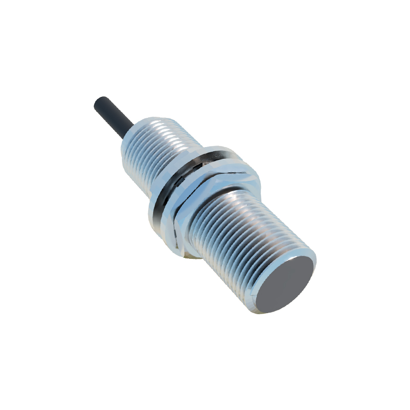
Regular verification and periodic re-calibration are essential components of a predictive maintenance program. Drift can occur over time due to component aging, accumulation of metallic debris on the sensing face, or mechanical shock. A documented calibration schedule, referencing the sensor's datasheet for recommended intervals and using traceable measurement tools, ensures long-term system integrity. For critical safety-related functions, such as in guarding systems, adherence to a strict calibration protocol is not optional but a regulatory imperative.
In conclusion, the calibration of proximity switch sensors is a precise engineering practice grounded in electromagnetic theory. It balances the nominal sensing distance with the stabilizing effect of hysteresis to achieve reliable operation in dynamic industrial environments. Mastering these principles—from understanding the influence of target material and mounting conditions to executing proper teach-in procedures—enables engineers to deploy these sensors with confidence, maximizing their performance, longevity, and contribution to overall system robustness.