Proximity sensors are fundamental components in modern industrial automation, robotics, and safety systems. Their primary function is to detect the presence or absence of an object within a specified range without physical contact. While much attention is given to sensing principles—inductive, capacitive, photoelectric, and ultrasonic—the electrical characteristics, particularly resistance, are equally critical for reliable system design, troubleshooting, and performance optimization. This article delves into the role of resistance in proximity sensors, exploring its impact on circuit behavior, signal integrity, and overall system health.
At its core, the resistance within a proximity sensor circuit is not a single, monolithic value but a combination of several factors. For an inductive proximity sensor, which detects metallic objects, the internal coil possesses a specific DC resistance. This resistance, often measured in ohms (Ω), is a function of the wire gauge, length, and material (typically copper). A typical sensor datasheet will specify a nominal coil resistance. This parameter is crucial for determining the sensor's current draw when powered by a DC source. Using Ohm's Law (V=IR), an engineer can calculate the steady-state current consumption. For instance, a 24V DC sensor with a coil resistance of 1200Ω will draw approximately 20mA. Exceeding the maximum current rating, often limited by this internal resistance and the driver circuitry, can lead to overheating and premature failure.
Beyond the simple DC coil resistance, the concept of impedance becomes paramount, especially for AC-operated sensors or when considering high-frequency switching. Impedance, encompassing both resistance and reactance (inductive or capacitive), dictates how the sensor interacts with alternating current. In an inductive sensor, the coil's inductive reactance increases with frequency, affecting the sensor's response time and its compatibility with certain control systems. A mismatch in impedance between the sensor and the programmable logic controller (PLC) input module can result in insufficient signal current, causing unreliable detection. Therefore, consulting the sensor's output characteristics (NPN sinking vs. PNP sourcing) and the input impedance of the controller is essential for a robust interface.
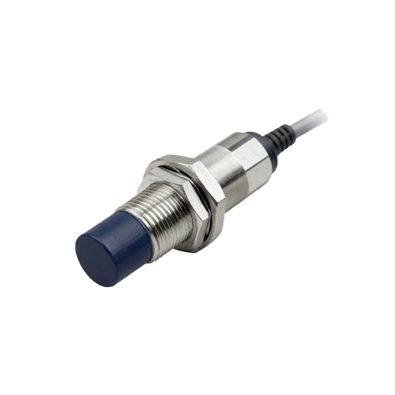
The output stage of a solid-state proximity sensor introduces another layer of resistance consideration. Most modern sensors employ a transistor output (typically an NPN or PNP configuration). When the sensor is in the "on" state (object detected), the output transistor acts like a switch with a very low resistance, allowing current to flow to the load. This is often called the "saturation resistance" or "on-state resistance" (Rds(on) for MOSFET outputs). A low on-state resistance minimizes voltage drop across the sensor, ensuring the full supply voltage is available for the load (e.g., a PLC input, relay coil, or indicator lamp). Conversely, a high on-state resistance can cause a significant voltage drop, potentially pulling the signal voltage below the PLC's recognized "on" threshold, leading to missed detections. Datasheets usually specify the maximum voltage drop at a rated load current, which is a direct reflection of this internal resistance.
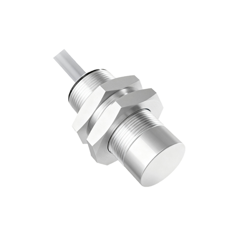
Environmental factors exert a profound influence on sensor resistance. Temperature is the most significant. The copper wire in an inductive coil has a positive temperature coefficient; its resistance increases as temperature rises. In high-ambient-temperature environments, the coil resistance may increase by 30-40% compared to its room-temperature specification. This increase leads to a reduction in operating current, which might marginally affect the magnetic field strength and, consequently, the sensing distance. More critically, it increases I²R power losses within the coil, contributing to further temperature rise—a potential thermal runaway scenario in poorly designed enclosures. Humidity and contamination can also create leakage paths or even short circuits, drastically altering the effective resistance between terminals and the sensor housing, compromising insulation and creating safety hazards.
From a maintenance and troubleshooting perspective, measuring resistance is a primary diagnostic tool. A multimeter can be used to check the coil resistance of a two-wire AC sensor or the resistance between the output transistor terminals of a three-wire DC sensor. A reading of infinite resistance (open circuit) indicates a broken coil or a failed output transistor. A reading of zero or very low resistance (short circuit) suggests an internal short. Comparing measured values against the manufacturer's specifications can quickly isolate a faulty sensor. However, it is vital to disconnect the sensor from power before taking any resistance measurements to avoid damaging the multimeter or the sensor's internal electronics. For capacitive sensors, which are sensitive to dielectric changes, resistance measurements are less indicative of health, and functional testing with a target is preferred.
In system design, understanding the cumulative resistance of the entire circuit is key. This includes the sensor's internal resistance, the resistance of the interconnecting wires (which can be substantial over long runs), and the input resistance of the receiving device. Voltage drop across long cable runs can be calculated using the formula V_drop