In the realm of industrial automation and electrical engineering, proximity sensors are indispensable components for non-contact object detection. A fundamental aspect of integrating these devices into schematic diagrams and control system layouts is understanding their standardized circuit symbols. These symbols, defined by international standards such as IEC 60617 and ANSI/IEEE Std 315, provide a universal graphical language that allows engineers across the globe to design, interpret, and troubleshoot complex circuits efficiently and accurately.
Unlike basic passive components, the circuit symbol for a proximity sensor encapsulates its function and output type within a simple geometric shape. The most common base symbol is a diamond or a square rotated 45 degrees to form a diamond shape. This diamond represents the sensing face or active area of the device. Within or adjacent to this diamond, critical functional information is added to specify the sensor's technology and output characteristics.
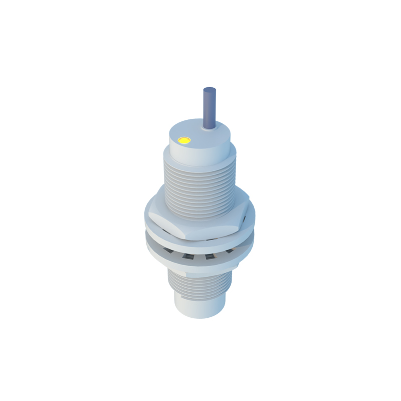
The primary distinction in symbols arises from the underlying detection technology. For inductive proximity sensors, which detect metallic objects, the standard symbol is the diamond with two parallel lines inside, representing the coil of the oscillator circuit. This is often accompanied by the abbreviation 'L' or 'IND' placed near the symbol. Capacitive proximity sensors, capable of detecting both metallic and non-metallic materials, are denoted by a diamond with two parallel plates inside, symbolizing the capacitive plates, and may be marked with 'C' or 'CAP'. For photoelectric sensors, the symbol typically deviates, using a pair of icons: a diode-like symbol with arrows for the emitter and a transistor-like symbol for the receiver, connected by dashed lines indicating the light beam.
The output type of the sensor is another critical element encoded in the symbol. This is represented by the standard symbols for switches placed in line with the sensor's connection lines. A normally open (NO) contact, or "make" contact, is shown as a switch that is open (not touching) in its non-activated state. When the sensor detects a target, this switch closes to complete the circuit. Conversely, a normally closed (NC) contact, or "break" contact, is depicted as a closed switch in the non-activated state, which opens upon detection. For solid-state outputs like NPN (sinking) or PNP (sourcing) transistors, the symbol incorporates the standard transistor symbol (with collector, emitter, and base) adjacent to the sensor diamond, clearly indicating the output polarity and configuration. The power supply connections, typically labeled as +V (or Vcc) and 0V (or GND), are also shown.
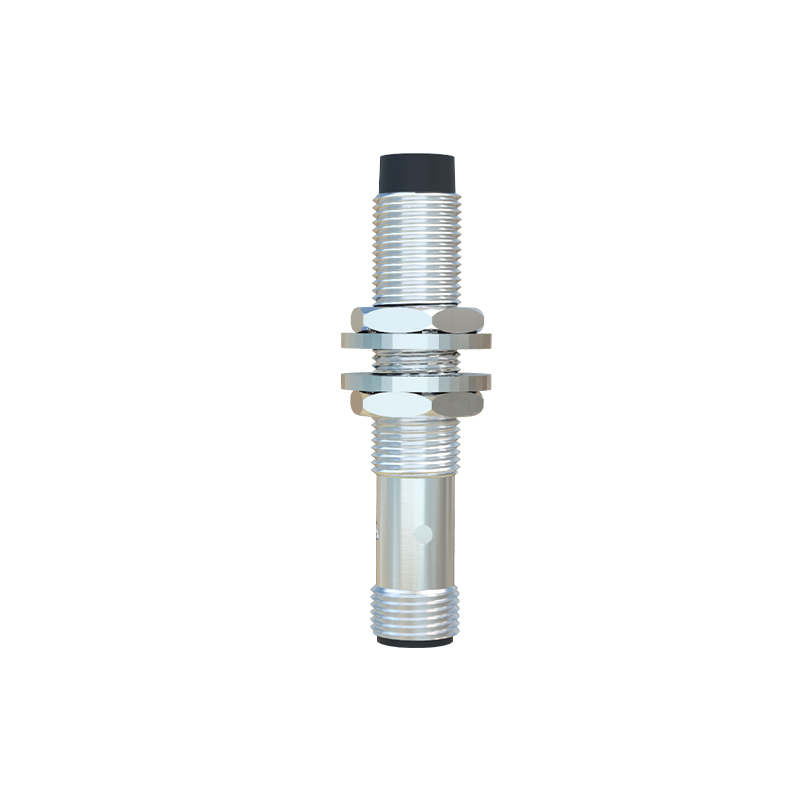
A complete proximity sensor symbol on a schematic will therefore combine these elements. For instance, a 3-wire DC inductive proximity sensor with a PNP normally open output would be drawn with a diamond containing two lines (inductive), a transistor symbol for PNP configuration, and an open switch symbol on the output line. The three connection points would be clearly labeled: +V, Output, and 0V. Two-wire AC/DC sensors, which act as variable impedance switches, are often represented simply by the sensor diamond in series with a standard switch symbol and the load.
Adherence to these standardized symbols is not merely academic; it is crucial for practical engineering. It prevents misinterpretation during the panel building phase, ensures correct wiring, and accelerates fault diagnosis. When a technician sees the specific symbol on a print, they immediately know whether they need to connect a metallic target, what voltage to supply, and what logic state (sourcing or sinking current) to expect from the output wire. In complex systems with dozens of sensors, this clarity is paramount for safety and functionality.
Furthermore, modern schematics created in EDA (Electronic Design Automation) software libraries are built around these standards. Engineers must select the correct symbol from the library to ensure the bill of materials is accurate and the electrical design data is consistent throughout the project lifecycle, from design to commissioning to maintenance.
In conclusion, the circuit symbols for proximity sensors are a concise yet powerful form of communication. They distill the sensor's core technology—inductive, capacitive, or photoelectric—and its electrical output behavior into an immediate visual cue. Mastery of these symbols, as defined by IEC and ANSI/IEEE standards, is an essential skill for any electrical engineer or technician working in automation, enabling precise design, error-free installation, and efficient troubleshooting of modern industrial control systems.