In the vast landscape of industrial automation and control systems, proximity sensors stand as fundamental components for non-contact object detection. Among the various configurations, the Normally Closed (NC) proximity sensor offers a distinct operational logic that is critical for specific safety and control applications. This article delves into the working principles, key characteristics, practical applications, and essential selection criteria for normally closed proximity sensors, providing a comprehensive guide for engineers and technicians.
At its core, a proximity sensor detects the presence or absence of an object within its sensing range without physical contact. It does so by emitting an electromagnetic field or a beam of electromagnetic radiation and looking for changes in the field or return signal. The terms "Normally Closed" and "Normally Open" (NO) refer to the electrical state of the sensor's output circuit when no target (the object to be detected) is present within its nominal sensing range.
A Normally Closed proximity sensor is characterized by its output being in a "closed" or "ON" state when it is in its normal, non-activated condition—that is, when no target is within the sensing field. In this resting state, electrical current can flow through the output circuit. When a target enters the sensing field and activates the sensor, the output circuit opens, turning the output "OFF" and interrupting the current flow. This behavior is the inverse of a Normally Open sensor, which has an open circuit when idle and closes the circuit upon detection.
This operational principle is typically implemented using solid-state switching elements like transistors. For a 3-wire DC sensor with an NPN output transistor configuration, a Normally Closed sensor will have the load connected between the sensor's output wire (often black) and the positive voltage supply (V+). In its normal state, the NPN transistor is saturated, allowing current to sink from the load, through the output, to common negative (0V). When activated by a target, the transistor turns off, stopping the current flow. For PNP output configurations, the logic is analogous but with opposite voltage polarities.
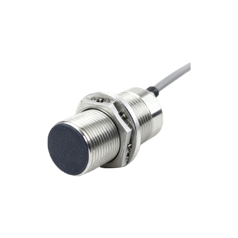
The choice between NC and NO configurations is not arbitrary; it is driven by specific application requirements, primarily concerning safety and system logic. Normally Closed sensors are frequently employed in safety-critical applications. The fundamental rationale is based on the "fail-safe" principle. Consider a safety interlock on a machine guard door. If a Normally Closed sensor is used to monitor whether the door is closed, the control circuit is complete (allowing machine operation) only when the door is securely shut. If the sensor fails—for instance, due to a wire break, power loss, or internal component failure—the circuit will open, mimicking the state of an open door and causing the machine to stop. This failure mode defaults to the safer state, preventing accidental operation. Using a Normally Open sensor in this scenario could be dangerous, as a sensor failure might keep the circuit closed (falsely indicating a closed door) even if the door is open.
Beyond safety, NC sensors are integral to control systems where the default "ON" state is necessary for process initiation or where the logic of a PLC (Programmable Logic Controller) program is simplified by using a sensor that is active when no target is present. For example, in a conveyor system tracking gaps between products, an NC sensor positioned along the line would be "ON" when no product is under it. The transition to "OFF" would signal the leading edge of a product, which can be a more straightforward trigger for a counter or timer.
When selecting a Normally Closed proximity sensor, several technical parameters must be carefully evaluated. The sensing range, defined as the maximum distance at which the sensor can reliably detect a standard target, is paramount. The target material also influences performance; inductive sensors detect metals, while capacitive sensors can detect both metallic and non-metallic materials. The housing material (e.g., stainless steel, nickel-plated brass, PBT plastic) must withstand the environmental conditions, including exposure to chemicals, moisture (IP rating), temperature extremes, and physical impacts. Electrical specifications such as operating voltage, output current capacity, and switching frequency (response time) must match the control system's requirements. Finally, the physical form factor—tubular, rectangular, or slot-style—must suit the mechanical mounting constraints.
Installation and wiring require attention to detail. Ensuring the correct voltage polarity, providing adequate shielding for cables in electrically noisy environments, and maintaining the proper mounting distance from metal surfaces (to avoid side-effects) are crucial for reliable operation. It is also vital to understand how the NC output integrates with the downstream controller. Many modern PLC input cards can be configured to source or sink current, and the sensor's output type (NPN/NC or PNP/NC) must be compatible.
In troubleshooting, understanding the NC logic is key. A common diagnostic step is to observe the sensor