In industrial automation and control systems, proximity sensors are indispensable components for non-contact detection of metallic or non-metallic objects. Their reliability hinges significantly on one critical factor: correct installation distance. This parameter, often referred to as the nominal sensing distance (Sn), is not merely a suggestion but a foundational engineering specification that dictates sensor performance, longevity, and system safety. Misunderstanding or neglecting its importance can lead to erratic operation, premature failure, or even hazardous conditions.
The core principle behind a proximity sensor's operation involves an electromagnetic field generated by its sensing face. When a target enters this field, it causes a change in oscillation amplitude or eddy currents, which the sensor's circuitry detects. The specified nominal sensing distance (Sn) is the theoretical, ideal distance at which a standard target under defined conditions will be reliably detected. It is crucial to understand that Sn is determined under laboratory conditions: at 23°C (73°F) with a supply voltage at nominal rating and using a prescribed standard target (typically a square of mild steel, Fe 360, with a side length equal to the sensor's diameter or the diameter of its sensing face).
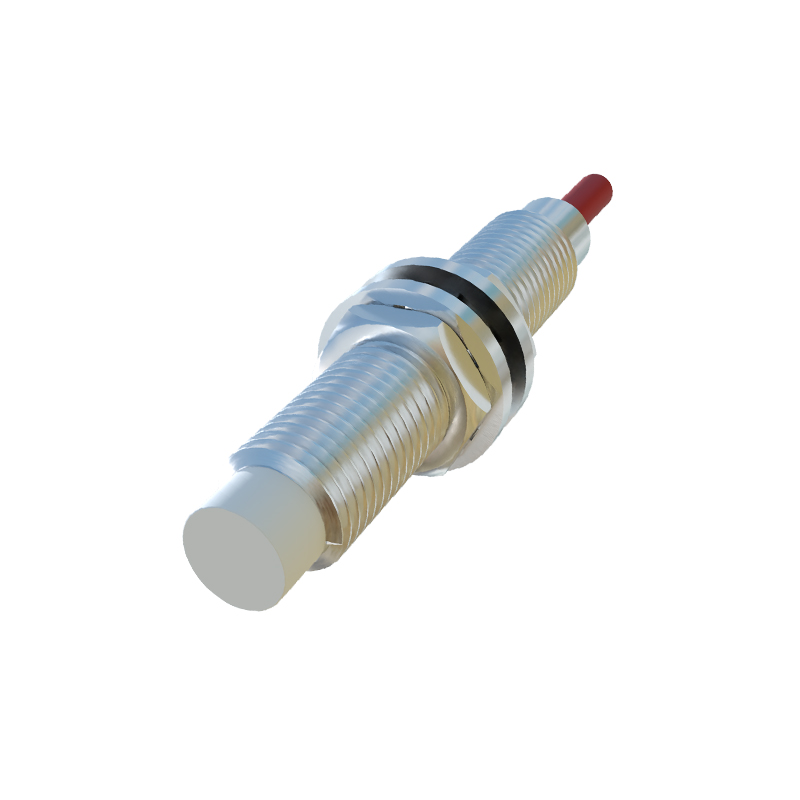
In real-world applications, these ideal conditions rarely exist. Therefore, the concept of the usable sensing distance (Su) or operating distance is introduced. This is the distance at which the sensor will switch under actual operating conditions, accounting for manufacturing tolerances, temperature fluctuations, and supply voltage variations. Industry standards (like IEC 60947-5-2) define this with a correction factor. For instance, a factor of 0.9 means the guaranteed operating distance is 90% of Sn. Engineers must always design based on Su, not Sn, to ensure a safety margin.
Several key factors necessitate adjustments to the nominal distance:
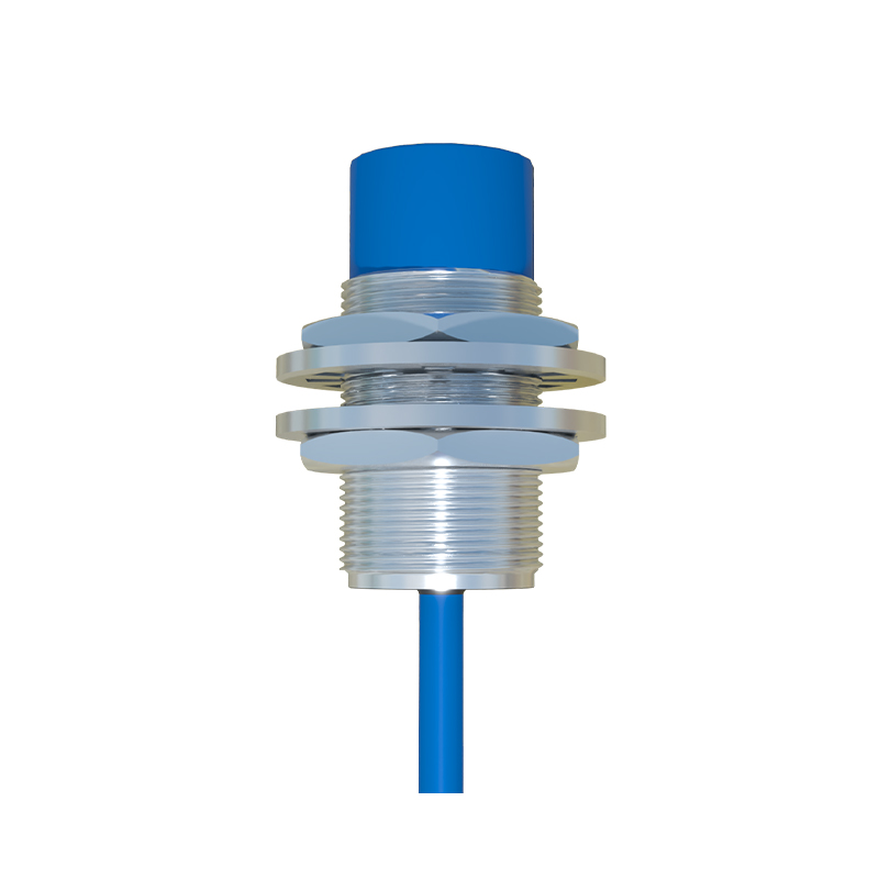
1. Target Material: The sensing distance is calibrated for mild steel. For other metals, a reduction factor must be applied. Stainless steel (non-magnetic austenitic grades like 304) typically reduces the sensing distance to about 70-80% of Sn. Copper and aluminum, being non-ferrous, reduce it even more drastically, often to 30-40% of Sn. For capacitive sensors detecting non-metals, material density and dielectric constant become the primary factors.
2. Target Size and Shape: The standard target is a square with a side equal to the sensor diameter. If the target is smaller, the effective sensing distance decreases. A cylindrical target will also have a different effective distance compared to a flat plate. The target must fully cover the active sensing area for reliable detection at the rated distance.
3. Temperature Effects: Extreme temperatures affect the sensor's electronic components and the physical properties of the target. High temperatures can reduce the effective sensing distance. Always consult the sensor's datasheet for derating curves, which show the permissible sensing distance as a function of ambient temperature.
4. Flush vs. Non-Flush Mounting: This is a critical distinction, primarily for inductive sensors. Shielded (flush-mountable) sensors have their sensing field concentrated directly in front of the face. They can be installed flush in metal without affecting operation but have a shorter Sn. Non-shielded (non-flush) sensors have an extended sensing range and a larger lateral field but must have a clearance zone of non-metallic material around them (specified in the datasheet) to prevent false triggering from the mounting nut or surrounding metal.
Installation Best Practices:
Maintain the Safety Margin: Never install the sensor at exactly the nominal distance. A common rule of thumb is to use 70-80% of the rated Su for the actual installation gap. This accounts for mechanical tolerances in the machine, vibration, thermal expansion, and target wear.
Consider Approach Direction: For optimal performance, the target should approach the sensor perpendicular to its sensing face. Angular approaches can reduce the effective distance.
Mind the Surroundings: Ensure no other metal objects (like machine frames, other sensors, or fasteners) are within the sensor's lateral sensing area, especially for non-flush types. Mutual interference can occur if two similar sensors are mounted too closely face-to-face or side-by-side; maintain the minimum separation distance specified by the manufacturer.
Account for Speed and Duty Cycle: For high-speed applications, the target's velocity and the sensor's response time must be considered. The effective "window" for detection becomes smaller. Ensure the sensor is positioned so the target is within the Su for a duration longer than the sensor's response time.
Verify with the Actual Target: After installation, always perform a functional test with the real target material, under normal operating conditions (powered, at temperature), to verify reliable switching. Use an oscilloscope or PLC input