In the intricate world of industrial automation, proximity sensors stand as silent sentinels, crucial for detecting the presence or absence of objects without physical contact. Their reliability directly impacts production line efficiency, safety, and overall equipment effectiveness (OEE). However, even the most robust sensors can encounter issues, leading to costly downtime. This is where the concept of a dedicated Proximity Sensor Debugging Center becomes invaluable. This guide outlines a systematic, engineer-centric approach to diagnosing and resolving proximity sensor malfunctions within such a focused troubleshooting environment.
The first pillar of an effective debugging center is a standardized diagnostic procedure. Upon receiving a sensor flagged for malfunction, the initial step involves a thorough visual inspection. Look for signs of physical damage, contamination from metal chips, oil, or coolant, and verify the integrity of the cable and connector. Following this, basic electrical tests are paramount. Using a multimeter, measure the supply voltage at the sensor's terminals to ensure it matches the specified range (commonly 10-30V DC for inductive types). Check for short circuits or open circuits in the wiring. For 3-wire sensors, verifying the correct wiring of brown (L+), blue (L-), and black (output) wires is essential.
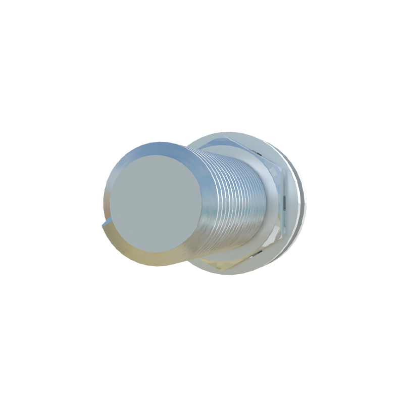
The core of the debugging center's capability lies in functional testing under simulated real-world conditions. A well-equipped center should have test benches that replicate various operational parameters. Key tests include:
1. Sensing Distance Verification: Using precision-calibrated targets (e.g., mild steel for inductive sensors), measure the actual sensing distance against the sensor's rated nominal sensing distance (Sn). A significant deviation often indicates internal component failure or misalignment.
2. Hysteresis Evaluation: Check the difference between the switch-on point (as the target approaches) and the switch-off point (as the target recedes). Abnormal hysteresis can cause erratic switching.
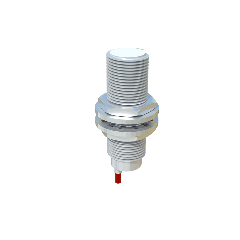
3. Response Time and Frequency Testing: Subject the sensor to a target moving at a known, adjustable speed to verify its maximum switching frequency. A slow response may fail to detect fast-moving objects on a conveyor.
4. Environmental Interference Testing: Expose the sensor to potential interferents present in its original environment. For inductive sensors, test for the influence of different metals (factor-1 corrections). For capacitive sensors, test for changes in humidity or non-target material proximity. Ultrasonic and photoelectric sensors should be tested for acoustic noise or ambient light interference, respectively.
Understanding failure modes is critical. Common inductive proximity sensor issues include reduced sensing range (often from accumulated metallic dust on the face), complete failure due to overload or short circuit, or erratic output from electrical noise. Capacitive sensors may false-trigger due to moisture or material buildup. Photoelectric sensors suffer from lens contamination or misalignment. The debugging center should correlate symptoms with these common failures to expedite repairs.
Beyond physical repair, a modern debugging center integrates data logging and analysis. Recording performance metrics from each debugged sensor—such as operating voltage tolerance, temperature drift, and output stability—builds a valuable database. This data can identify recurring failure patterns linked to specific machine models, environmental conditions, or sensor batches, enabling proactive maintenance and informed procurement decisions.
Finally, the center serves as a knowledge hub. Documenting every case with findings, solutions, and root cause analysis creates a powerful troubleshooting manual. This repository accelerates future diagnostics and is an excellent training resource for junior engineers. Emphasizing preventive measures, such as proper sensor selection (considering environmental IP ratings, temperature, and target material), correct installation (maintaining proper clearance from metal surrounds), and routine cleaning schedules, can significantly reduce failure rates.
In conclusion, a dedicated Proximity Sensor Debugging Center is not merely a repair station; it is a strategic asset for any serious industrial operation. By implementing a structured, data-driven approach to fault diagnosis, functional verification, and knowledge management, engineers can transform reactive troubleshooting into a proactive practice that enhances system reliability, reduces unplanned downtime, and optimizes the lifecycle cost of automation components. The goal is to ensure that every sensor returning to the production floor operates with certified precision and reliability.