In industrial automation and control systems, metal proximity switch sensors are critical components for detecting the presence or absence of metallic objects without physical contact. Their reliability directly impacts operational efficiency, safety, and maintenance costs. As an experienced electrical engineer, I will outline key methods to assess the quality of these sensors, covering performance indicators, testing procedures, and common failure modes.
First, understand the basic working principle. Inductive proximity sensors generate an electromagnetic field. When a metal target enters this field, it induces eddy currents, causing a change in the oscillator's amplitude. This change triggers the output circuit to switch states. The sensor's quality can be evaluated through several technical parameters.
Key Performance Indicators:
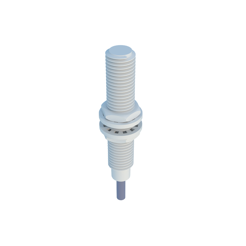
1. Sensing Distance: The nominal sensing distance (Sn) is specified for a standard target (usually mild steel). High-quality sensors maintain consistent sensing distances within tolerances, even under varying temperatures or voltage fluctuations. A significant deviation indicates wear or internal component degradation.
2. Repeat Accuracy: This refers to the sensor's ability to consistently detect a target at the same position. Premium sensors offer repeat accuracy within microns, ensuring precise machine operations. Test by repeatedly moving a target to the same point and observing output stability.
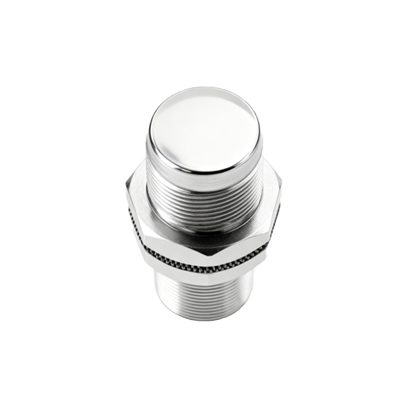
3. Hysteresis: The difference between the switch-on and switch-off points. Adequate hysteresis prevents chattering (rapid on/off cycling) when a target is near the sensing limit. Quality sensors have optimized hysteresis values, typically 3-10% of Sn, documented in datasheets.
4. Response Time: The time delay between target detection and output change. Fast response times (microseconds to milliseconds) are vital for high-speed applications. Slow response may signal circuit issues or contamination.
5. Environmental Robustness: Industrial environments expose sensors to temperature extremes, humidity, vibration, and chemicals. Check IP (Ingress Protection) and IK (Impact Protection) ratings. A good sensor withstands conditions like -25°C to 70°C, IP67 sealing, and resistances to oils or coolants.
Testing Procedures:
- Visual Inspection: Examine the housing for cracks, corrosion, or damage. Ensure the sensing face is clean; accumulated metal chips or dirt can reduce effectiveness.
- Electrical Testing: Use a multimeter to measure supply voltage and output signals. For a 3-wire DC sensor, verify voltage between brown (positive) and blue (negative) wires. With a target present, the output wire (black or white) should switch to supply voltage (for PNP) or 0V (for NPN). Inconsistent readings suggest internal faults.
- Oscilloscope Analysis: Connect an oscilloscope to monitor the output waveform. A clean, sharp transition indicates healthy switching. Noise, ringing, or slow rise times may point to electromagnetic interference or component aging.
- Functional Test: Perform a bench test with a standardized metal target (e.g., 1mm thick mild steel square). Measure the actual sensing distance and compare it to Sn. Gradually move the target to check for smooth operation without false triggers.
- Load Testing: Connect the sensor to its typical load (e.g., a relay or PLC input). Monitor for voltage drops or overheating, which could denote output transistor issues.
Common Failure Modes and Quality Red Flags:
1. Intermittent Operation: Often caused by loose wiring, damaged cables, or internal solder joint failures. High-vibration environments accelerate such wear.
2. Reduced Sensing Range: This may result from degraded oscillator components, coil damage, or a weakened electromagnetic field due to aging.
3. False Triggering: Electromagnetic interference (EMI) from nearby motors or frequency drives can cause erratic behavior. Quality sensors include shielding and filtering circuits.
4. Output Stuck On/Off: A permanently activated or deactivated output usually indicates a blown output transistor or power supply reversal damage.
5. Short Lifespan: Inferior materials or poor manufacturing lead to early failures. Brands with proven track records and certifications (e.g., UL, CE) typically offer better durability.
Preventive Maintenance Tips:
- Regularly clean sensing surfaces with a soft cloth.
- Ensure proper installation, avoiding excessive stress on cables.
- Use surge protectors in circuits with inductive loads to prevent voltage spikes.
- Keep sensors away from strong magnetic fields or other EMI sources.
In summary, assessing a metal proximity switch sensor's quality involves verifying technical specifications, conducting systematic tests, and recognizing failure patterns. Investing in reputable brands and adhering to maintenance schedules can minimize downtime and enhance system reliability. Always consult the manufacturer's datasheet for specific guidelines, as parameters vary by model and application.