Proximity sensors are indispensable components in modern industrial automation, providing non-contact detection of metallic and, in some cases, non-metallic objects. Their reliability hinges on correct parameter configuration, a task that demands a precise understanding of both sensor specifications and application requirements. This guide details the critical parameters for inductive and capacitive proximity switches, offering configuration best practices for optimal performance.
The cornerstone of configuration is understanding the sensor's core specifications. The sensing distance (Sn) is nominal and typically defined for a standard target (e.g., mild steel). Actual sensing distance can vary with target material, size, and shape. A crucial rule is to install the sensor at 70-80% of its rated Sn to account for environmental factors like temperature drift and supply voltage variations. The hysteresis parameter, the difference between the switch-on and switch-off points, is vital for preventing output chatter when a target is at the detection boundary. Most sensors have a built-in hysteresis of 3-20% of Sn; understanding this prevents instability in control logic.
Output configuration is a primary setup step. For DC sensors, the choice between NPN (sinking) and PNP (sourcing) outputs must align with the PLC or controller input module's architecture. Wiring an NPN sensor to a PNP-compatible input will result in failure. For AC/DC universal sensors, verify the correct wiring for the supplied voltage. The output function, normally open (NO) or normally closed (NC), must be selected based on the safety and logic requirements of the machine. An NO configuration closes the circuit upon detection, while an NC configuration opens it. Fail-safe designs often utilize NC wiring.
Response time and switching frequency are dynamic parameters critical for high-speed applications. Response time is the delay between target detection and output state change. Switching frequency, measured in Hertz, defines how many detection cycles per second the sensor can handle. For a fast-moving object on a conveyor, a sensor with a 1kHz switching frequency can theoretically detect objects spaced as close as 1ms apart. Exceeding this frequency leads to missed detections. Always select a sensor with a switching frequency at least 1.5 times higher than the maximum required application frequency.
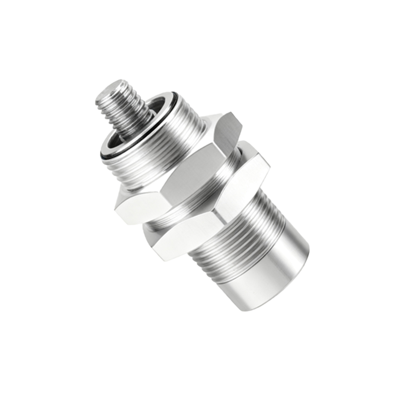
Environmental compensation and setup aids are advanced features on modern sensors. Temperature compensation circuits adjust the sensing point to maintain stability across the operating temperature range. For inductive sensors detecting different metals, a potentiometer or teach-in function allows adjustment of the sensitivity to suit a specific target material (e.g., aluminum versus steel). This is essential when the target's material has a lower conductivity or permeability than standard steel.
Immunity to interference is a configurable aspect on many premium sensors. Electrical noise from variable frequency drives (VFDs) or welding equipment can cause false triggering. Sensors with adjustable shielding (shielded vs. unshielded) offer flexibility: shielded types have a focused sensing field ideal for flush mounting in metal, while unshielded types offer a longer range but are susceptible to lateral metal interference. Additionally, some models feature a response delay setting, which can be increased to ignore brief, spurious signals caused by noise or vibration.
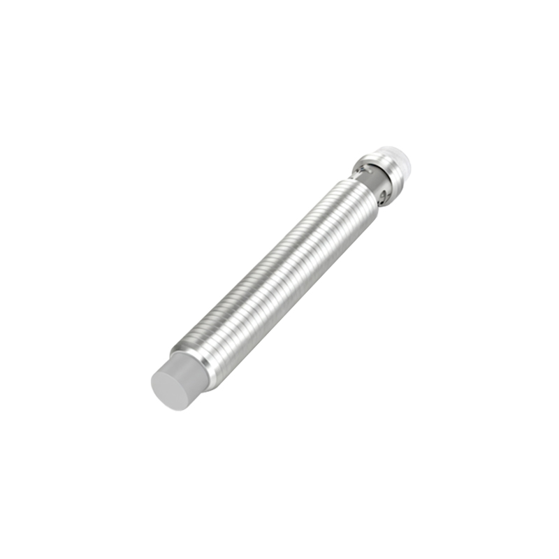
Installation geometry profoundly affects performance. The target size must meet the sensor's minimum requirement, typically a square plate with sides equal to the sensor's face diameter or the rated sensing distance, whichever is larger. For cylindrical targets, effective sensing distance is reduced. The approach direction is also key; the target should approach the sensor's sensing face perpendicularly. Axial approaches to the side of a cylindrical sensor barrel will reduce effective range.
Finally, a systematic approach to configuration is recommended. First, define the application's physical requirements: target material, size, required detection distance, and available space. Second, select the sensor type (inductive for metals, capacitive for non-metals or level detection) and housing style. Third, based on the electrical system, choose the correct output type (PNP/NPN, NO/NC) and voltage. Fourth, calculate the required switching frequency and response time. Fifth, upon installation, use the sensor's indicators (often a built-in LED) to verify proper detection and adjust sensitivity if necessary. Always consult the manufacturer's datasheet, as specifications and adjustment methods vary between models. Proper configuration ensures not only operational reliability but also extends sensor lifespan by preventing electrical overload and mechanical stress, forming a critical pillar of efficient and safe automation system design.