Proximity sensors are indispensable components in modern industrial automation, playing a critical role in object detection, position sensing, and machine control without physical contact. Their reliability hinges not only on selecting the correct sensor type (inductive, capacitive, or photoelectric) but also on precise and proper wiring. Incorrect wiring can lead to sensor failure, erratic machine behavior, or even damage to the control system. This guide provides a detailed overview of standard proximity sensor wiring methods, configurations, and essential considerations for electrical engineers and technicians.
The foundation of proximity sensor wiring lies in understanding the three primary electrical configurations: 2-wire, 3-wire, and 4-wire (or 5-wire for certain analog or IO-Link models). Each serves distinct purposes and interfaces differently with Programmable Logic Controllers (PLCs) and other control devices.
1. 2-Wire Proximity Sensors
The simplest configuration, 2-wire sensors, are connected in series with the load (e.g., a PLC input module, relay coil). They function similarly to a mechanical switch. One wire connects to the positive DC supply voltage (or one AC phase), and the other wire connects to the load. When the sensor detects a target, it closes the internal switch, allowing current to flow and energize the load.
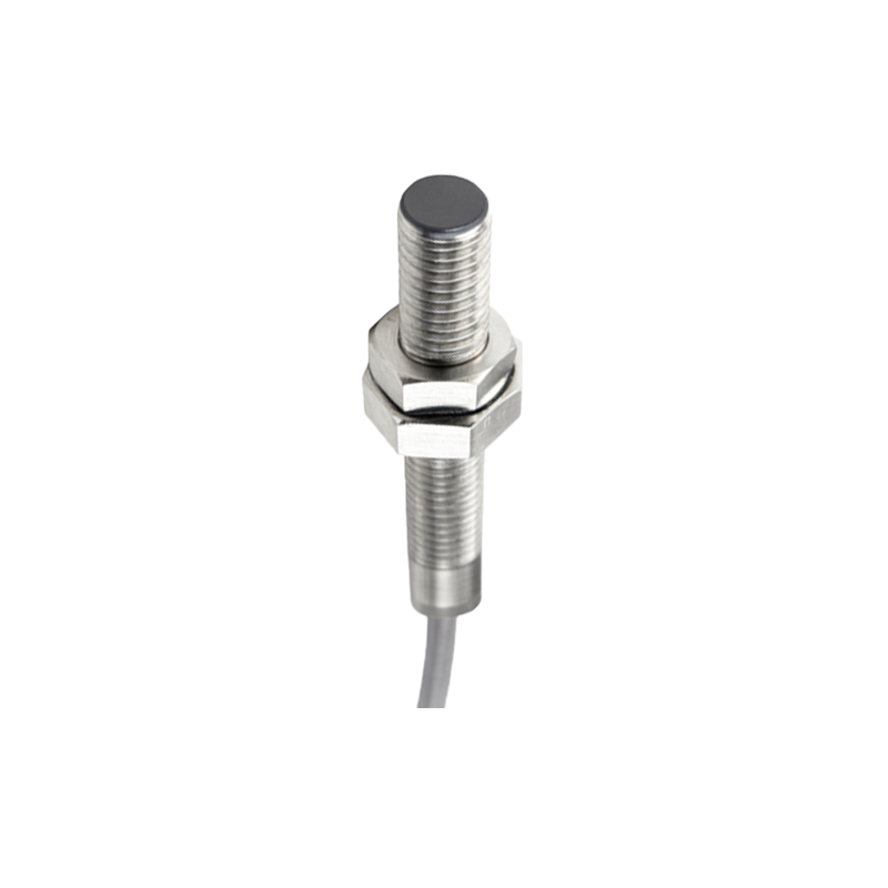
Key Consideration: These sensors have a residual voltage drop (leakage current) when in the "off" state. This residual current must be lower than the minimum holding current of the load (especially critical for relays) to prevent unintended activation. Always verify compatibility with the PLC input module's specifications regarding leakage current.
2. 3-Wire Proximity Sensors
This is the most common configuration in DC systems, offering superior performance and easier integration. 3-wire sensors have separate paths for power supply and the switching signal, typically comprising a brown wire (positive supply, +V), a blue wire (negative supply, 0V or common), and a black wire (switching output).
The output type is crucial and must match the control system input:
NPN (Sinking) Output: The black output wire acts as a switch to the negative (0V) line. When active, it connects the load to ground. The load is connected between the positive supply (+V) and the black wire. This configuration is often used with PLCs where the input common is connected to +V.
PNP (Sourcing) Output: The black output wire acts as a switch to the positive (+V) line. When active, it supplies voltage to the load. The load is connected between the black wire and the negative (0V) line. This is commonly used with PLCs where the input common is connected to 0V.
Mixing NPN and PNP wiring with an incompatible PLC input circuit will result in non-operation. Always consult both the sensor datasheet and the PLC hardware manual.
3. 4-Wire (or Dual Output) Sensors
These sensors incorporate both a Normally Open (NO) and a Normally Closed (NC) output in one device, typically with a shared common. They provide wiring flexibility for control logic requiring complementary signals or for implementing redundancy in safety monitoring circuits. The wiring follows the same NPN/PNP principles for each output channel.
Wiring Procedures and Best Practices:
1. Power Off: Always disconnect power before starting any wiring work.
2. Verify Specifications: Confirm the sensor's operating voltage (e.g., 10-30V DC, 20-250V AC), output type (NPN/PNP, NO/NC), and current rating.
3. Select Cable: Use shielded, multi-conductor cable for longer runs or in electrically noisy environments. Connect the shield to a proper functional earth ground at the control panel end only, avoiding ground loops.
4. Connection: Strip wires to the recommended length. Use ferrule crimps for a secure, reliable connection in terminal blocks. Ensure tight connections to prevent arcing and heat buildup.
5. Polarity: For DC sensors, strict polarity observance is mandatory. Reverse polarity can instantly destroy the sensor.
6. Load Protection: Incorporate protective devices such as fuses or circuit breakers in the supply line. For inductive loads (relays, solenoids), use suppression elements (flyback diodes, varistors, or RC networks) across the load to protect the sensor's solid-state switch from voltage transients.
7. Testing: After wiring, apply power and test the sensor's operation with its target. Use a multimeter to verify the output voltage state (high or low) in both sensing and non-sensing conditions.
Troubleshooting Common Wiring Issues: