In the realm of industrial automation and machinery, proximity sensors are indispensable components for non-contact detection. A critical yet often overlooked aspect of these sensors is their electrical connector. This teardown guide provides a detailed, step-by-step visual and analytical breakdown of a standard industrial proximity sensor connector, offering insights into its construction, wiring, and maintenance considerations.
The connector in focus is a typical 4-pin, M12-style threaded circular connector, commonly used with inductive proximity sensors in IP67-rated environments. Before beginning any disassembly, ensure the sensor is disconnected from its power source and control system. Safety is paramount.
Step 1: External Inspection and Disconnection
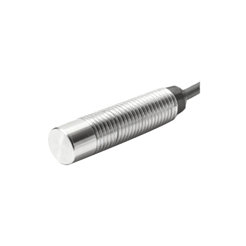
The connector consists of two main halves: the sensor-integrated plug (male pins) and the cable-mounted socket (female receptacles). The brass or nickel-plated brass housing features a robust threaded coupling nut. Note the orientation key to prevent incorrect mating. Unscrew the coupling nut by rotating it counterclockwise. Gently pull the two halves apart.
Step 2: Socket Half (Cable Side) Disassembly
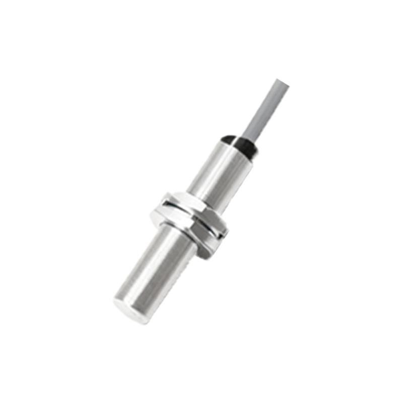
The cable-side socket houses the female terminals. Using a small flat-head screwdriver, carefully pry open the rear cable gland or strain relief assembly. This component secures the cable and provides environmental sealing. Once loosened, you can slide it back along the cable. Next, locate the terminal housing block inside the socket body. It is often a plastic insert. Depress the small plastic locking tabs (one per terminal) using a terminal release tool or a very fine pick. While depressing the tab, gently pull the connected wire from the rear to extract the crimped terminal from the housing. Repeat for all wires (typically brown for +V, blue for 0V, black for signal output, and white for a second output or diagnostic). Inspect each terminal for corrosion, proper crimping, and wire integrity.
Step 3: Plug Half (Sensor Side) Disassembly
The sensor-side plug is often potted with epoxy or sealed to protect the internal sensor electronics from moisture and vibration. Disassembly here is typically for major repair only and may not be reversible. If the plug is a separate module wired to the sensor, you may find small screws securing the back shell. Remove these screws. Inside, the male pins are fixed within an insulated insert. The pins are usually soldered directly to the sensor's PCB traces. Do not attempt to remove these pins unless necessary, as soldering integrity is crucial for reliability.

Step 4: Component Analysis
Housing: Made of metal for EMI shielding and mechanical strength. The threads are precision-cut to ensure a secure, vibration-proof connection and maintain the IP rating.
Seals: Observe the orange silicone or rubber O-ring seated in a groove on the plug housing. This single seal is responsible for the primary water and dust ingress protection. Check for cracks, flattening, or deterioration.
Terminal Inserts: The plastic (often PBT) insert that holds the terminals provides pin alignment and electrical insulation between contacts.
Terminals: Gold-plated brass terminals ensure low contact resistance and corrosion resistance. The crimp style is a common industry standard (e.g., for wire gauges 18-22 AWG).
Cable Gland: Comprises a compression nut, a seal, and a clamping collet. It grips the cable jacket firmly to absorb mechanical strain, preventing tension from transferring to the electrical connections.
Step 5: Reassembly Notes
Reassembly is the reverse order. Critical points:
1. Ensure the O-ring is clean, lubricated with a tiny amount of silicone grease (if recommended), and properly seated in its groove.
2. Re-insert terminals into their respective numbered positions in the housing insert until a definitive click is heard, confirming the locking tab has engaged.
3. Tighten the cable gland nut firmly but do not over-torque, which can damage the cable or seal.
4. When mating the connector halves, align the orientation key and hand-tighten the coupling nut before final tightening with a wrench, following the manufacturer's specified torque (usually 0.5-0.8 Nm for M12).
Common Failure Points Identified:
Failed or missing O-ring leading to moisture ingress and corrosion.
Poor crimps on terminals causing intermittent signals or open circuits.
Broken wire strands at the crimp point due to excessive flexing or an improperly adjusted cable gland.
Cross-threading of the coupling nut, damaging the housing threads.
Contamination (oil, metal chips) on the terminal contacts.
Understanding this internal anatomy empowers technicians to perform effective troubleshooting, preventive maintenance, and correct field repairs