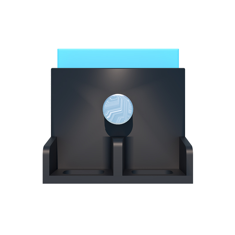
In the realm of industrial automation and motion control, speed sensor proximity switches stand as critical components for monitoring rotational or linear speed, detecting object presence, and ensuring operational safety. Unlike simple on/off proximity sensors, these devices are engineered to provide a continuous or pulsed output signal whose frequency is directly proportional to the speed of a moving target, typically a gear tooth, cam, or specially designed rotor.
The core operating principle hinges on non-contact sensing technology. Inductive proximity switches are the most prevalent for metallic targets. They contain an oscillator circuit that generates a high-frequency electromagnetic field at the active face. When a ferrous metal target, such as a gear tooth, enters this field, eddy currents are induced, causing a change in the oscillator's amplitude. This change is detected by a threshold circuit, which then switches the solid-state output. By counting the pulses generated per unit time as gear teeth pass by, the rotational speed (RPM) can be precisely calculated. For non-metallic applications, capacitive or ultrasonic proximity sensors may be employed, though they are less common for high-speed, high-precision rotational sensing.
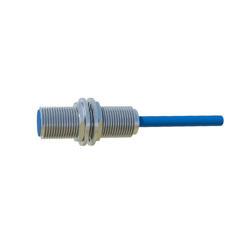
Key performance specifications define their suitability for various applications. Sensing range, typically from a few millimeters up to 40mm for inductive types, must be carefully selected to ensure reliable detection without physical contact. Switching frequency, measured in Hertz (Hz), dictates the maximum speed the sensor can reliably detect; a 5 kHz sensor can handle 5000 pulses per second. Output types are crucial: NPN (sinking) or PNP (sourcing) transistor outputs are standard for DC models, providing a digital pulse train. Some advanced models offer analog outputs (4-20 mA or 0-10 V) proportional to speed, or even IO-Link digital communication for integrated parameter setting and diagnostics. Environmental robustness is paramount, with ingress protection ratings (e.g., IP67, IP69K) for dust and water resistance, and wide operating temperature ranges to withstand harsh plant conditions.
The applications for speed sensor proximity switches are vast and integral to modern industry. In conveyor systems, they monitor belt speed for synchronization, slip detection, and overload protection. Integrated into motor and gearbox assemblies, they provide essential feedback for variable frequency drive (VFD) control, enabling precise speed regulation and torque control. They are indispensable in automotive manufacturing for monitoring engine RPM, wheel speed (forming part of ABS systems), and production line sequencing. Within packaging machinery, they ensure precise timing for cutting, filling, and labeling operations based on web speed. Furthermore, they serve as vital safety devices, acting as overspeed or underspeed monitors for fans, pumps, and centrifuges, triggering alarms or shutdowns to prevent catastrophic failure.
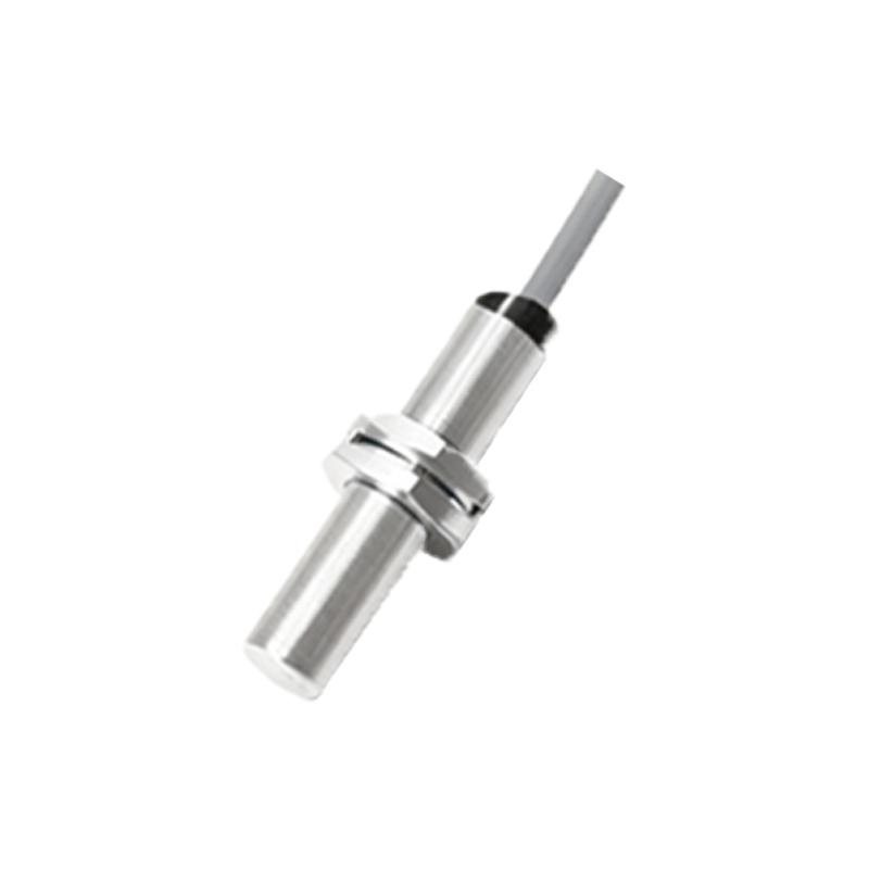
Selecting the correct speed sensor proximity switch requires a methodical analysis of the application parameters. First, identify the target material (ferrous metal, non-ferrous metal, plastic) to determine the sensing technology. Next, define the required sensing distance, considering installation tolerances and potential target wear. The maximum expected speed, translated into a required switching frequency (Pulses per Second = (RPM Number of Teeth) / 60), must be within the sensor's specification. Electrical compatibility is essential: match the supply voltage (e.g., 10-30 VDC, 90-250 VAC) and output configuration (NPN/PNP) with the control system's input module. The housing material (stainless steel, nickel-plated brass, PBT plastic) should be chosen for chemical and mechanical resistance. For demanding environments, look for enhanced features like weld-field immunity, short-circuit protection, and extended temperature ratings.
Installation and alignment are critical for reliable operation. The sensor must be mounted securely to minimize vibration, with the sensing face positioned perpendicular to the target's path of movement. The gap between the sensor and the target should be set at 50% to 80% of the rated sensing distance to account for thermal expansion, bearing play, and mechanical runout. For gear tooth sensing, the tooth width and gap should ideally be larger than the sensor's face diameter. Regular maintenance, though minimal, involves periodic inspection for physical damage, buildup of debris on the sensing face, and verification of signal integrity using an oscilloscope or a PLC counter diagnostic.
In conclusion, speed sensor proximity switches are sophisticated yet robust devices that translate physical motion into actionable electronic data. Their role in enabling precise control, enhancing productivity, and safeguarding equipment is fundamental across countless industries. A thorough understanding of their principles, careful selection based on application demands, and proper installation are the keystones to leveraging their full potential for efficient and reliable automation system performance.