In the realm of industrial automation and control, selecting the right sensing technology is paramount for system efficiency, safety, and reliability. Two fundamental components often at the forefront of this decision are speed sensors and proximity switches. While both serve critical roles in monitoring and control loops, their operating principles, applications, and output characteristics differ significantly. This guide provides a technical comparison to aid engineers and technicians in making informed choices for their specific projects.
Fundamental Operating Principles
A proximity switch, often termed a proximity sensor or prox switch, is a non-contact device designed to detect the presence or absence of a target object within its sensing range. It does not require physical contact. The most common types are inductive, capacitive, and photoelectric. Inductive proximity switches, for instance, generate an electromagnetic field. When a metallic object enters this field, it causes a change in the oscillation amplitude, which is detected by the sensor's circuit, triggering a solid-state output switch (typically PNP or NPN). The key output is a simple binary signal: ON or OFF, object present or not present. They are excellent for position detection, part counting, and end-of-travel limits.
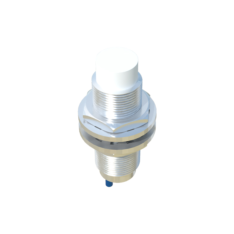
A speed sensor, conversely, is specifically engineered to measure the rotational or linear speed of a target. Common types include magnetic (variable reluctance), Hall-effect, and optical encoders. A magnetic speed sensor, for example, consists of a permanent magnet and a coil. When a ferrous gear tooth or other ferromagnetic target passes the sensor face, it disrupts the magnetic flux, inducing a voltage pulse in the coil. The frequency of this pulse train is directly proportional to the speed of the target. The output is an analog signal (sine wave or variable voltage) or a digital pulse train whose frequency must be interpreted by a controller, tachometer, or PLC counter module to derive speed (RPM, m/s, etc.).
Key Technical Differences and Selection Criteria
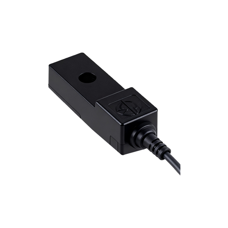
1. Output Signal: This is the most critical distinction. Proximity switches provide a discrete digital signal. Speed sensors provide a continuous or pulsed signal whose frequency or amplitude correlates to velocity.
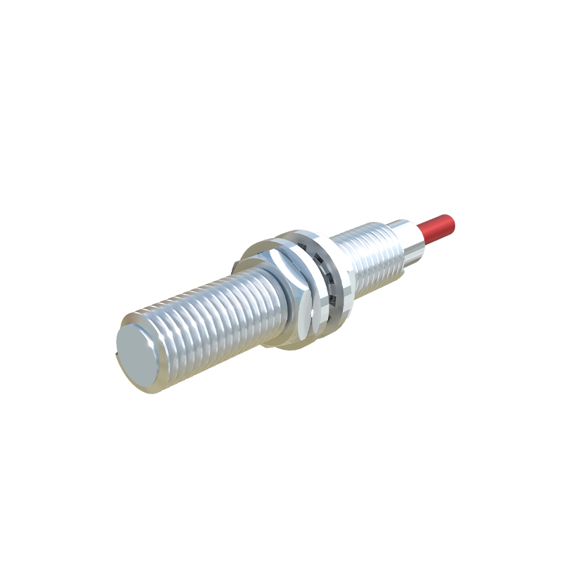
2. Application Purpose: Use a proximity switch for presence/absence detection, object counting (where speed is irrelevant), or position verification. Use a speed sensor when you need to measure rotational speed, monitor for overspeed/underspeed conditions, or calculate rate-based parameters like flow or conveyor belt speed.
3. Target Material: Inductive proximity switches only detect metals. Capacitive types can detect metals, liquids, plastics, and other materials. Speed sensors typically require a ferrous target (for magnetic types) or a coded wheel/reflective mark (for optical encoders).
4. Installation and Setup: Proximity switches are generally simpler to integrate; you set the sensing distance and connect the output to a digital input. Speed sensors require more consideration regarding gap (air gap), target geometry (gear tooth size), and signal conditioning. The output often needs filtering, amplification, or conversion in the control system.
5. Performance Parameters: For proximity switches, key specs are sensing distance, repeat accuracy, switching frequency, and housing material. For speed sensors, critical specs are minimum/maximum detectable speed, pulses per revolution (PPR), signal amplitude, and phase accuracy (for directional sensing).
Hybrid and Advanced Applications
In modern systems, the lines can blur. Some Hall-effect sensors can function as both a proximity switch (detecting the presence of a magnetic field) and a speed sensor by pulsing with each passing magnet. Encoders provide not just speed but also precise positional feedback. Furthermore, the raw pulse output from a speed sensor can be fed into a frequency-to-voltage converter to create an analog speed signal, or into a PLC's high-speed counter for precise digital speed calculation and logic control.
Conclusion and Best Practices
The choice between a speed sensor and a proximity switch is not a matter of which is better, but which is appropriate for the required function. Start by clearly defining the control objective: Is it detection or measurement? For simple state detection (is the machine home? is a part in place?), a robust proximity switch is often the most cost-effective and reliable solution. For monitoring conveyor speed, protecting machinery from overspeed, or providing feedback for closed-loop speed control, a dedicated speed sensor is indispensable.
Always consult manufacturer datasheets for specific environmental ratings (IP, temperature, vibration), electrical requirements, and output compatibility with your controller. Proper selection, installation, and shielding of cables (especially for analog speed signals) are crucial to mitigate electrical noise and ensure long-term, trouble-free operation in demanding industrial environments.