Proximity sensors are indispensable components in modern industrial automation, playing a critical role in object detection, position sensing, and process control without physical contact. Their correct installation and wiring are paramount for ensuring system reliability, safety, and optimal performance. This guide provides a detailed overview of standard proximity sensor wiring methods, adhering to common industry practices and electrical standards.
Understanding Sensor Types and Outputs
Before delving into wiring, it's crucial to identify the sensor type and its output configuration. The two primary categories are based on the detection principle: Inductive (for detecting metallic objects) and Capacitive (for detecting both metallic and non-metallic objects). More fundamentally for wiring, sensors are classified by their output circuitry:
1. PNP (Sourcing) Output: The output signal wire switches the positive voltage (+V) to the load. When active, the output provides a positive voltage.
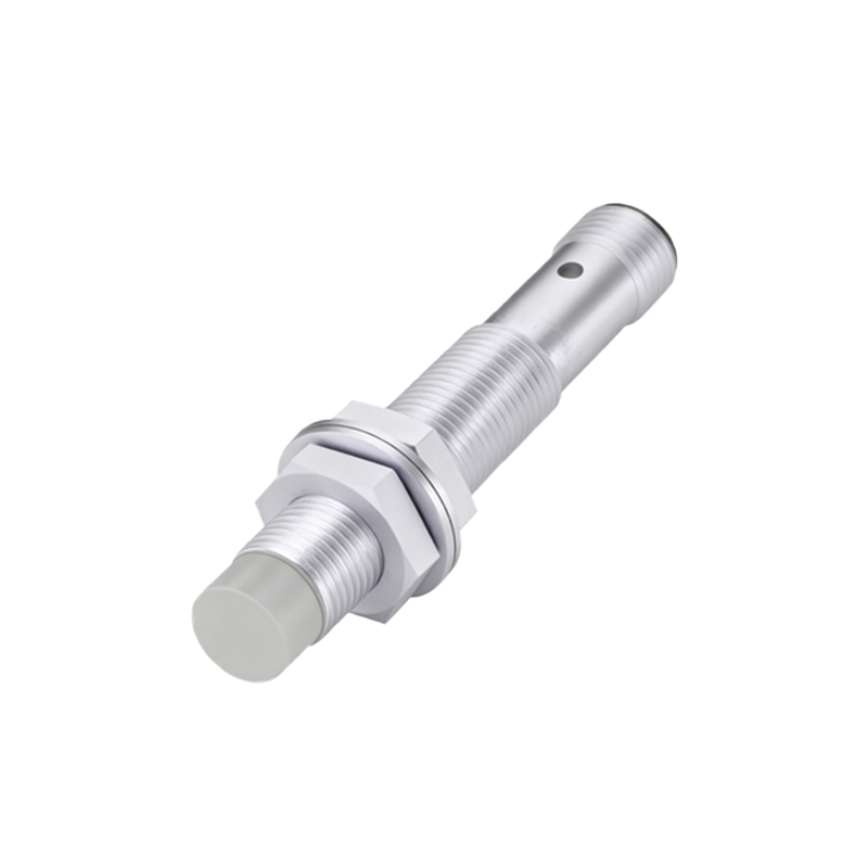
2. NPN (Sinking) Output: The output signal wire switches the ground or negative (-) connection to the load. When active, it provides a path to ground.
3. Analog Output: Provides a continuously variable signal (e.g., 0-10V or 4-20mA) proportional to the distance to the target.
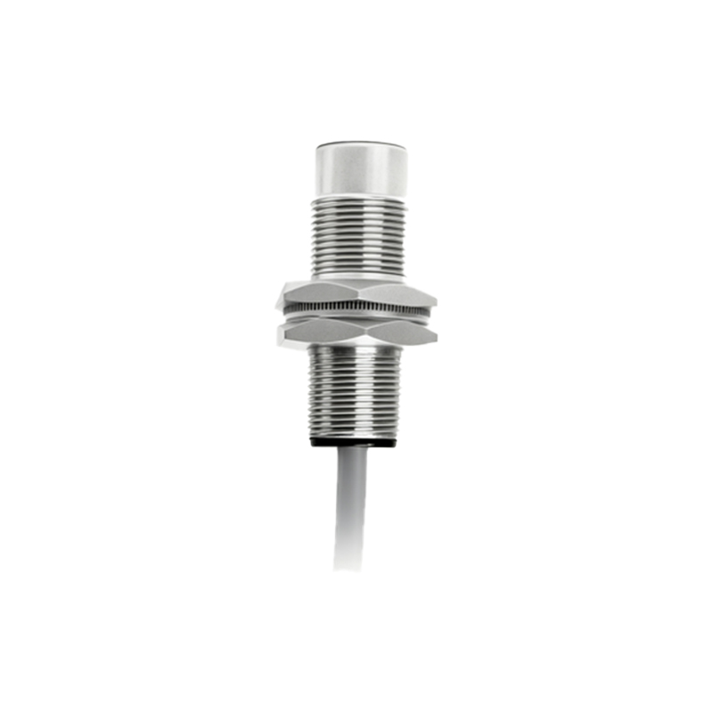
4. Push-Pull (Complementary) Output: Combines PNP and NPN in one device, allowing flexibility in connection.
Additionally, sensors come as 2-wire, 3-wire, or 4-wire devices. 3-wire sensors are the most common for DC models, requiring separate wires for power supply positive, power supply negative/common, and the switched output signal.
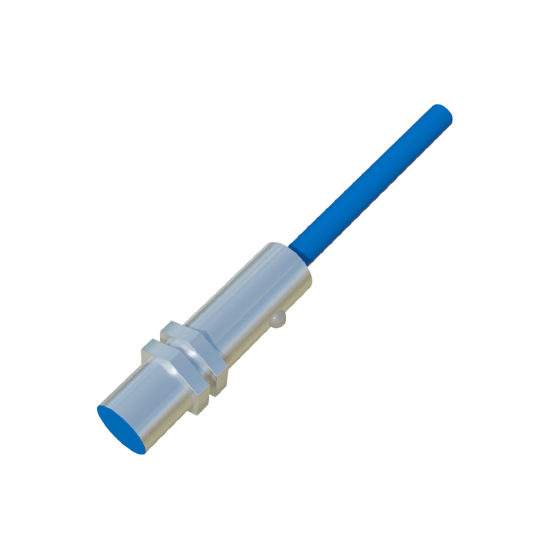
Standard 3-Wire DC Sensor Wiring
This is the most frequent wiring scenario. A typical 3-wire DC proximity sensor has three distinct leads, often color-coded as Brown, Blue, and Black (following international convention IEC 60947-5-2).
Brown Wire: Connect to the positive DC supply voltage (+V). Typical voltages are 10-30V DC.
Blue Wire: Connect to the negative DC supply voltage (0V) or common ground.
Black Wire: This is the output signal wire. Its function depends on whether the sensor is PNP or NPN.
Wiring a PNP Sensor:
1. Connect Brown to +24V DC (example).
2. Connect Blue to 0V DC (Common).
3. Connect the Black output wire to one terminal of your load (e.g., a PLC input, relay coil, or indicator lamp).
4. Connect the other terminal of the load to the 0V DC (Common).
When the PNP sensor detects an object, it switches the Black wire to +24V, sourcing current from the sensor to the load, completing the circuit to common.
Wiring an NPN Sensor:
1. Connect Brown to +24V DC.
2. Connect Blue to 0V DC (Common).
3. Connect the Black output wire to one terminal of your load.
4. Connect the other terminal of the load to the +24V DC supply.
When the NPN sensor detects an object, it switches the Black wire to 0V, sinking current from the load to the sensor (to ground), completing the circuit to positive.
Crucial Considerations for Reliable Operation
Power Supply: Always use a regulated, stabilized DC power supply within the sensor's specified voltage range. Ripple and noise can cause erratic operation.
Load Compatibility: Ensure the load (PLC input module, relay, etc.) is compatible with the sensor's output type (PNP vs. NPN). Mismatching can lead to malfunction or damage. Many PLC input modules can be configured for either sourcing (PNP) or sinking (NPN) inputs.
Shielding and Cable Routing: In electrically noisy environments (near VFDs, large motors, welding equipment), use shielded cables. Connect the cable shield to a proper earth ground at the control panel end only. Route sensor cables separately from power cables to minimize inductive coupling.
Short-Circuit and Overload Protection: Incorporate fuses or circuit breakers in the supply lines. Some sensors have built-in short-circuit protection, but external protection is a standard safety practice.
Wiring Integrity: Use proper crimping tools and terminals. Ensure connections are tight and protected from vibration. For harsh environments, select sensors with appropriate IP (Ingress Protection) ratings and use conduit or cable glands.
Leakage Current: Be aware that solid-state outputs have a small leakage current (typically< 1.8mA) even when "off."