In the realm of industrial automation and control systems, proximity sensors are indispensable components. They provide non-contact detection of metallic or, in some cases, non-metallic objects, enabling precise control, positioning, and safety functions. However, a persistent challenge that engineers and technicians face is sensor interference, which can lead to erratic behavior, false triggering, or complete failure. Understanding the root causes of this interference is crucial for ensuring system reliability and uptime. This article delves into the primary sources of interference affecting inductive and capacitive proximity sensors, the most common types used in industrial settings.
The most prevalent cause of interference is electromagnetic interference (EMI) or radio frequency interference (RFI). Industrial environments are rife with sources of electromagnetic noise. Variable frequency drives (VFDs) controlling motors, welding equipment, large solenoids, and even communication devices like walkie-talkies can generate powerful electromagnetic fields. These fields can induce unwanted voltages in the sensor's circuitry or its connecting cables. For inductive sensors, which operate by generating an electromagnetic field of their own, external EMI can distort this field, causing the sensor to detect a non-existent target or fail to detect a real one. Similarly, capacitive sensors, sensitive to changes in an electrostatic field, can be triggered by stray capacitance from nearby moving objects or even humidity changes, which are often exacerbated by EMI conditions.
Electrical noise on power supply lines is another critical factor. Proximity sensors, especially two-wire AC/DC types, are susceptible to voltage spikes, transients, and harmonics present on the main power line. These disturbances can originate from the switching of large inductive loads elsewhere on the same circuit. A voltage spike can momentarily saturate the sensor's electronics, causing a false pulse output. Furthermore, inadequate grounding or the use of a common ground path for high-power equipment and sensitive sensor circuits creates ground loops. Current flowing through these loops generates a voltage difference, which the sensor interprets as a signal, leading to instability.
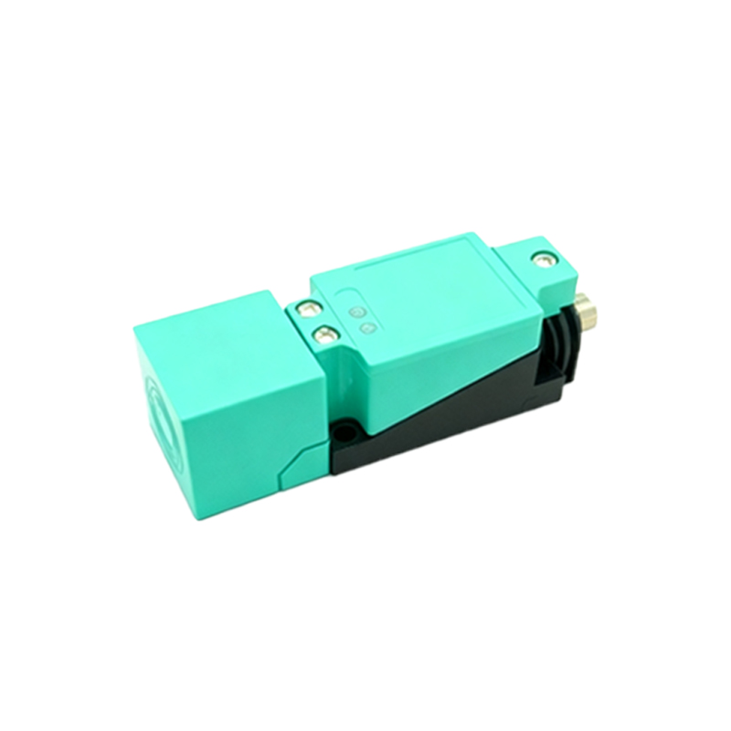
Physical and environmental factors also play a significant role. Mutual interference occurs when two or more proximity sensors are mounted too close to each other. The oscillating electromagnetic field of one inductive sensor can affect the oscillator of its neighbor, potentially causing both to latch on or off incorrectly. The recommended mounting distance, typically three times the sensor's rated sensing distance, is often overlooked in space-constrained installations. For capacitive sensors, the buildup of dust, moisture, or chemical deposits on the sensing face can alter its dielectric properties, effectively changing its sensitivity and making it prone to interference from environmental conditions it was not calibrated for.
Improper installation and wiring practices are perhaps the most common, yet preventable, causes of interference. Using unshielded cables or failing to properly terminate the shield of a shielded cable invites EMI to couple directly onto the signal lines. Running sensor cables in the same conduit or cable tray as high-current AC power lines is a classic recipe for induced noise. Long cable runs without proper consideration for voltage drop or impedance can also make the signal more vulnerable to pickup. Additionally, using sensors with an incorrect voltage rating or connecting them to an unregulated power supply can lead to operational issues that mimic interference.
Mitigating these interference issues requires a systematic approach. Firstly, always select a sensor with an appropriate housing material (e.g., stainless steel for better shielding) and a design suitable for the electrical noise environment. Employing sensors with built-in surge protection and noise immunity features is advisable. Secondly, adhere strictly to proper installation guidelines: use shielded, twisted-pair cables, ground the shield at only one end (typically the controller end), and maintain maximum physical separation between signal cables and power lines. Implementing separate conduits is ideal. Power conditioning, such as using isolation transformers or line filters for the sensor circuit, can clean up noisy supplies. For mutual interference, ensure correct sensor spacing and, if possible, use sensors with different operating frequencies or synchronized models designed to prevent crosstalk.
In conclusion, interference in proximity sensors stems from a confluence of electromagnetic, electrical, physical, and installation-related factors. The harsh electrical landscape of modern industrial facilities makes immunity a key sensor specification. By comprehending the sources—be it EMI from drives, ground loops, sensor crowding, or subpar wiring—engineers can proactively design systems and specify components that minimize vulnerability. Regular maintenance, including cleaning sensor faces and checking cable integrity, further safeguards against intermittent problems. A thorough understanding of these interference causes is not merely academic; it is a fundamental requirement for achieving the precision, safety, and reliability expected in automated industrial processes.