In the realm of industrial automation, proximity switches are indispensable sensors for non-contact detection of metallic and, in some cases, non-metallic objects. A critical yet often nuanced specification for these devices is their operating frequency, also commonly referred to as the switching frequency or response frequency. This parameter fundamentally dictates the sensor's capability to detect objects in high-speed applications and is paramount for system design and reliability.
The operating frequency of a proximity switch is defined as the maximum number of switching cycles (ON/OFF operations) the sensor can perform per second, measured in Hertz (Hz). It represents the sensor's speed of response. This limit is governed by several intrinsic factors within the sensor's design. The core oscillator circuit, which generates the electromagnetic field for inductive sensors or the ultrasonic/capacitive field for other types, has a finite excitation and damping time. The signal conditioning electronics, including the amplifier, comparator, and output stage, also contribute to the total processing delay. For instance, after a target enters the sensing range, the oscillator's amplitude changes, this signal is amplified, compared to a threshold, and finally, the output transistor (PNP/NPN) switches state. The cumulative time of this sequence is the sensor's response time. The reciprocal of this response time (1/Response Time) gives a theoretical maximum frequency.
It is crucial to distinguish between two key metrics: response time and repeat accuracy. A high frequency does not equate to high positional repeatability. A sensor might switch at 5 kHz but have a hysteresis (the difference between the switch-on and switch-off points) of several micrometers, affecting precision placement tasks. Frequency speaks to speed; hysteresis speaks to consistency.
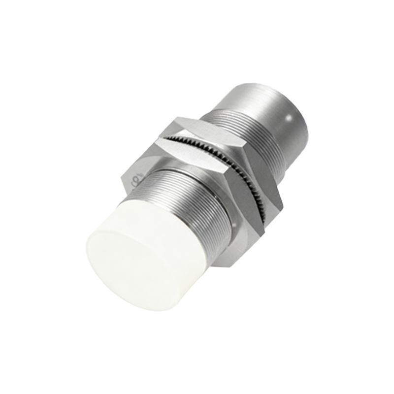
The frequency range varies significantly across different sensing technologies. Standard shielded inductive proximity sensors, common for detecting ferrous metals, typically offer frequencies from 500 Hz to 5 kHz. High-speed inductive models, often with reduced sensing ranges or specialized designs, can reach 10 kHz to 20 kHz. Capacitive sensors, used for non-metals, generally operate at lower frequencies, often below 100 Hz, due to the nature of dielectric constant measurement. Ultrasonic sensors fall into a similar lower frequency bracket for continuous measurement, though their pulse repetition rate can be high. Photoelectric sensors, depending on their modulation technique (e.g., pulsed LED), can achieve very high frequencies, from 10 kHz to over 50 kHz for specialized fiber-optic amplifiers, making them ideal for counting small, fast-moving parts.
Selecting a sensor with an appropriate frequency rating is a direct function of the application's demands. Key calculation parameters include the target object's size, the required detection distance, and most importantly, the linear speed of the object. The fundamental formula involves the object's speed (v) and its length (L) in the direction of travel. For reliable detection, the sensor's ON-time must be at least long enough for the electronics to register the target. A practical rule is that the minimum detectable object length should satisfy: L_min > v / f_max, where f_max is the sensor's maximum switching frequency. Conversely, for a given object size and speed, the required sensor frequency is f_required > v / L. For example, to detect a 5mm metal tab on a shaft rotating at 3000 RPM (circumferential speed ~0.785 m/s), the required frequency would be > 157 Hz. Choosing a sensor with a 1 kHz rating provides a comfortable safety margin.
In high-frequency applications, several pitfalls must be avoided. Electrical noise from variable frequency drives (VFDs), welding equipment, or power lines can induce false triggering in sensitive circuits, effectively limiting the usable frequency. Proper shielding, grounded metal mounting, and using sensors with robust noise immunity (e.g., DC models with surge protection) are essential. Thermal effects are another concern; continuous high-frequency switching increases internal power dissipation in the output stage. Exceeding the specified duty cycle can lead to overheating and premature failure. Mechanical mounting and vibration can also affect performance if not secure.
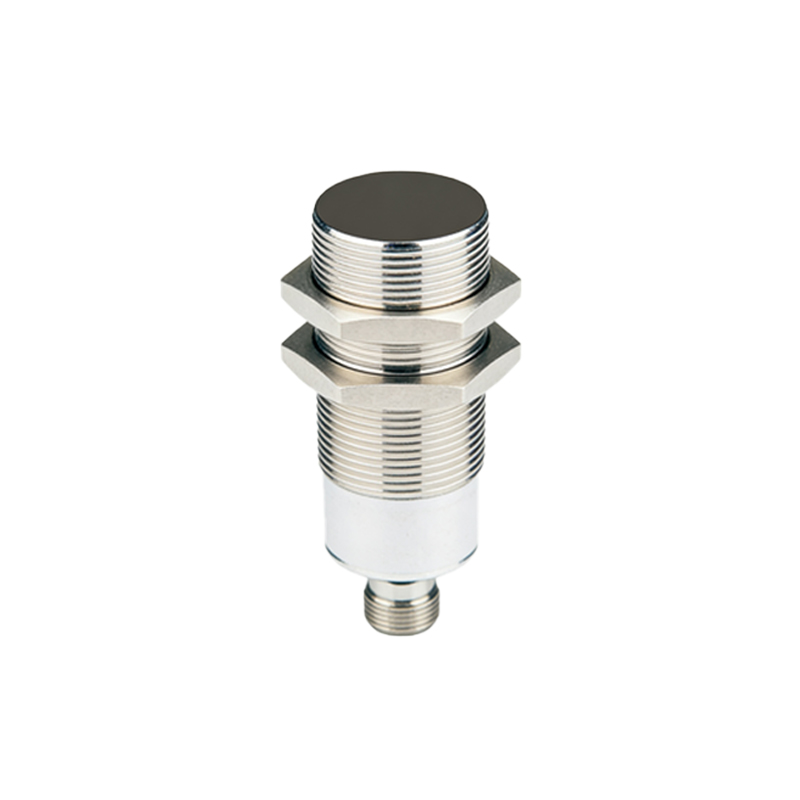
Modern advancements continue to push the boundaries. Sensors with ASIC (Application-Specific Integrated Circuit) technology offer faster, more stable oscillation and processing. IO-Link enabled smart sensors can provide diagnostic data, including cycle count and temperature, allowing for predictive maintenance and dynamic adjustment of parameters in some cases. For extreme speeds, such as monitoring turbine blades or high-velocity packaging lines, specialized high-frequency sensors or alternative technologies like laser-based systems become necessary.
In conclusion, the frequency range of a proximity switch is not a mere datasheet number but a vital performance characteristic that interfaces directly with mechanical system dynamics. A thorough understanding of the underlying technology, a precise calculation based on application kinematics, and consideration of the electrical and thermal environment are all required to select a sensor that ensures both high-speed performance and long-term reliability in demanding industrial